USD
USD INR
INR
Call Us Now
+91 9106756572
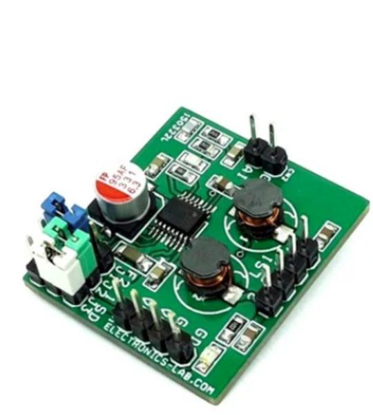
This is a compact size, mono, switch-mode (Class-D) audio power amplifier intended for multimedia and general-purpose high-power applications. It has greater than 87% efficiency and is capable of delivering 2W maximum continuous power to a 4Ω load. The project is designed to be driven by the line-out or headphone jack of a CD/MP3 player or to be directly connected to any audio source. The project includes header connectors for speakers, power supply, and audio input for quick connection. The project also has 3x jumpers for frequency selection and shutdown action. The project is built using the MAX4295 chip.
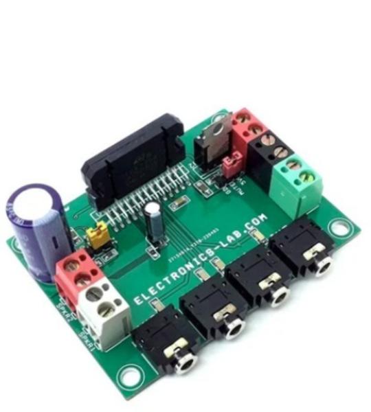
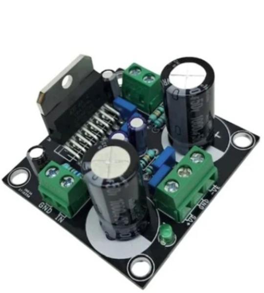
This is an AB class audio amplifier based on the TDA7388 chip and it is a great choice for car audio applications. This compact board has 4 channels each 26W with 4 ohms speaker. Then IC consists of a fully complementary PNP/NPN configuration and the TDA7388 allows a rail-to-rail output voltage swing with no need for bootstrap capacitors. The extremely reduced boundary components count allows very compact sets. The TDA7388’s inputs are ground-compatible and can stand very high input signals (±8 Vpk) without any performance degradation. The standard value for the input capacitors (0.1 µF) is adopted, and the low-frequency cut-off amount to 16 Hz. 4 x 3.5 mm stereo EP socket helps to feed audio signals, and the onboard screw terminal makes life easy for speaker connections, and the power supply input. Onboard jumpers are provided to select the standby and mute function. D1 indicates power present. Mounting a proper heatsink is very important for chip health.
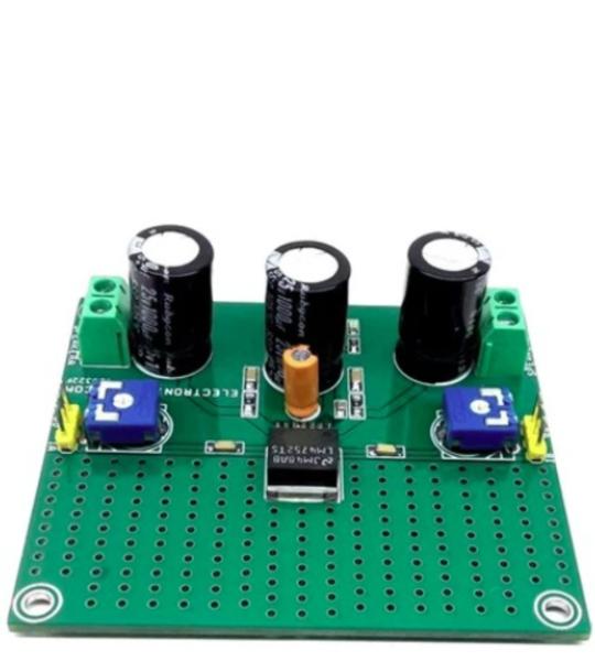
The Stereo Audio Amplifier project shown here is capable of delivering 2.5W per channel of continuous average output power to 4Ω loads using a single 12V supply at 10% THD+N. The project is built using the LM4752 chip. This chip is specifically designed for single supply operations and low external components count. The gain and bias resistors are integrated on-chip, resulting in a 2.5W stereo amplifier in a compact 7-pin TO263 SMD package. High output power levels at 12V supplies and low external component count offer high value for compact stereo and TV applications. Sufficient power dissipation is provided on PCB so no external heatsink is required for IC.
The 60 W Class-AB Audio Amplifier is a single-channel power amplifier board built around the STMicroelectronics TDA7296. This Class-AB amplifier is suited to a wide range of applications, including home stereo systems, self-powered speakers, and high-end televisions.
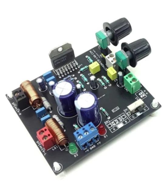
The stereo audio amplifier project shown here is capable of delivering typically 40W per channel continuous average output power into an 8Ω load with less than 0.1% (THD+N). The project is built using an LM4766 chip from Texas Instruments, The performance of the LM4766, utilizing its Self-Peak Instantaneous Temperature (°Ke) (Spike) Protection Circuitry, places it in a class above discrete and hybrid amplifiers by providing an inherently, dynamically protected Safe Operating Area (SOA). Spike Protection means that these parts are safeguarded at the output against overvoltage, undervoltage, overloads, including thermal runaway and instantaneous temperature peaks. Each amplifier within the LM4766 has an independent smooth transition fade-in/out mute that minimizes output pops. The IC’s extremely low noise floor at 2µV and its extremely low THD+N value of 0.06% at the rated power make the LM4766 optimum for high-end stereo TVs or mini-component systems.
Cookie preferences