USD
USD INR
INR
Call Us Now
+91 9106756572
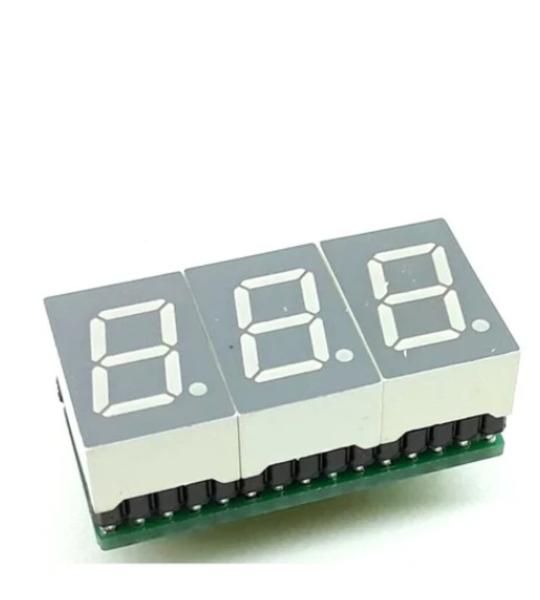
This is a 3 Digit 7-segment display project that contains 3 x Common Cathode displays, current limiting resistors or each LED segment, 3 x PNP Transistor on each common cathode for multiplexing etc. The project works with 5V TTL signals but can be optimized for 3.3V operations by reducing the current limiting resistors' value.
D116
This is a 3 Digit 7-segment display project that contains 3 x Common Cathode displays, current limiting resistors or each LED segment, 3 x PNP Transistor on each common cathode for multiplexing etc. The project works with 5V TTL signals but can be optimized for 3.3V operations by reducing the current limiting resistors' value.
https://en.wikipedia.org/wiki/Multiplexed_display
Arduino code is provided to test the board. The user will be able to create a 0 to 5V DC Voltmeter using this code. Upload the code to Arduino Uno, apply 0 to 5V to Analog Pin A0 to Measure the voltage. Refer Arduino pin configuration vs display bellow:
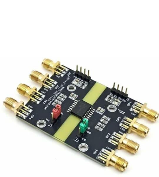
The project presented here is a high-speed, low-power 4-channel digital galvanic isolator. This innovative solution enables the transfer of digital signals between circuits with different power domains, achieving an impressive power consumption of as little as 0.74mW per channel at a data rate of 1 Mbps, while operating on a 1.8V supply. At the heart of this project is the MAX22445FAWE chip, which features reinforced isolation, allowing it to withstand a voltage rating of 5KV-RMS for 60 seconds. This robust design ensures reliable and secure signal transmission.
D101
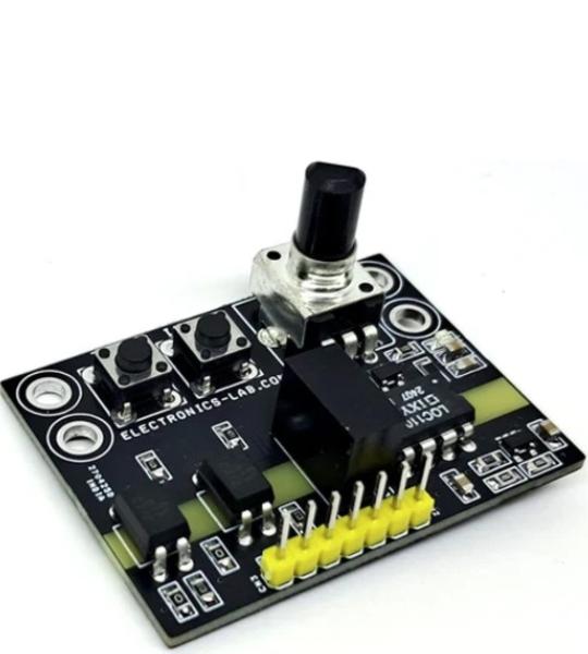
This is an Isolated Potentiometer Module that integrates a LOC110 linear optocoupler, an isolated DC-DC converter, an onboard 10K linear potentiometer, 2 x tactile switches, 2 x PC817 optocouplers, and supporting circuitry. It is designed for reliable use in VFD drives, process control, PLCs, automation systems, and other industrial applications where isolated analog signals and isolated switch inputs are required.
D102
Transmitter
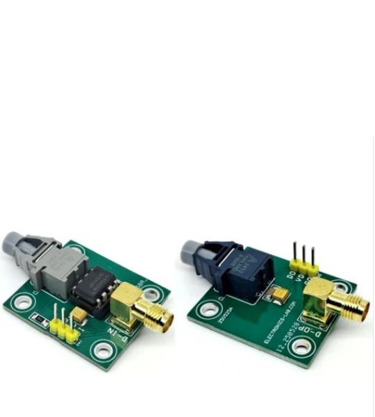
This module enables users to establish a versatile fiber-optic link for applications requiring a low-cost/high immunity solution. It transmits TTL source data over a fiber-optic connection, supporting transmission distances of up to 19 meters with standard fiber-optic cable and up to 53 meters with enhanced cable.
Receiver
This module enables users to create a versatile fiber-optic link for applications requiring a low-cost solution. This receiver module receives data through a fiber-optic link and outputs standard TTL-level signals. It supports transmission distances of up to 19 meters with standard fiber-optic cable and up to 53 meters with enhanced cable.
D103
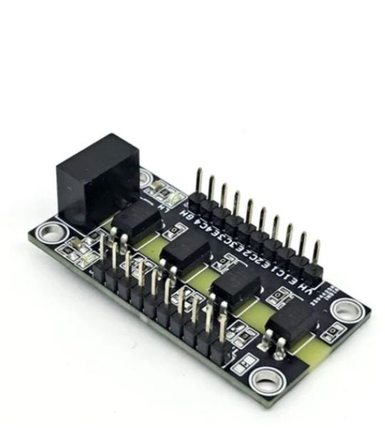
This is a 4-channel optocoupler module features 4x PC817 optocouplers and an onboard DC-DC converter. It provides reliable electrical isolation between the processor and the high-voltage side. The high-voltage side can be configured as either pull-up or pull-down, while the low-voltage side supports both common-cathode and common-anode configurations. Configuration is selectable via onboard resistors. The integrated 5 V DC-DC converter supplies power to the low-voltage side.
D104
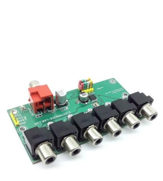
The project presented here is a video driver with 6 channel input selection using onboard jumpers or a microcontroller interface. The circuit features a wide dynamic range and frequency response. The IC can be used with low voltage starting at VCC=2.8V and the project supports a broad range of input signals, depending on whether or not a 6-dB video and video driver is included and what combination of sync tip clamp type and bias (resistor terminal) type input is used. RCA connectors are provided for video input and output connection. The header connector helps to power the board. Jumpers J2 to J3 are provided to select the input channels. 6-channel video selection can also be controlled using an external circuit or microcontroller by applying high or low TTL signal to CTLA, CTLB, CTLC, CTLD pins. In this case, use the center pins of jumper J1 to J4.
D105
Cookie preferences