USD
USD INR
INR
Call Us Now
+91 9106756572
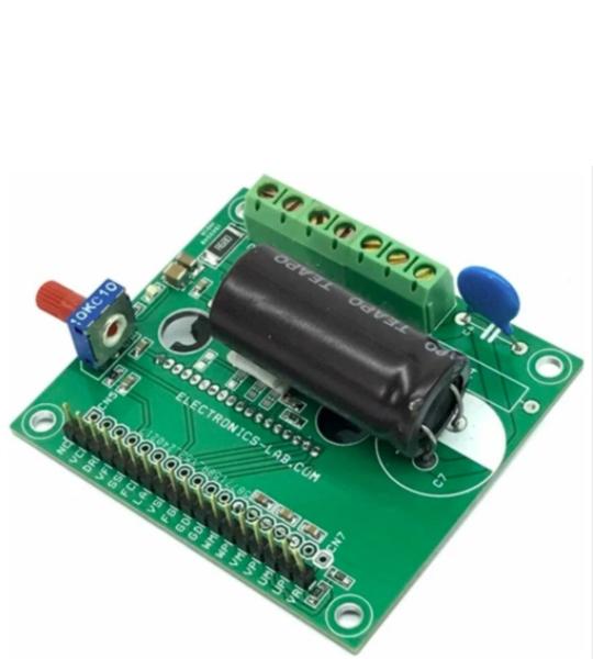
The project presented here is a three-phase sinewave PWM driver for high-voltage brushless motors. The board is built using TB67B000AHG chip, which is a high-voltage IC capable of handling 600V. The TB67B000AHG has a 2-in-1 (MCP) structure of controller (sine-wave PWM / wide-angle conduction) and a high-voltage driver. The rotation speed of a DC brushless motor can be controlled directly by the speed control signal (analog voltage) by an onboard trimmer potentiometer or from a microcontroller. The board supports a 3-phase BLDC motor with Hall sensors. On Board Trimmer, the potentiometer helps users to control the speed of the brushless motor.
The project presented here is a three-phase sinewave PWM driver for high-voltage brushless motors. The board is built using TB67B000AHG chip, which is a high-voltage IC capable of handling 600V. The TB67B000AHG has a 2-in-1 (MCP) structure of controller (sine-wave PWM / wide-angle conduction) and a high-voltage driver. The rotation speed of a DC brushless motor can be controlled directly by the speed control signal (analog voltage) by an onboard trimmer potentiometer or from a microcontroller. The board supports a 3-phase BLDC motor with Hall sensors. On Board Trimmer, the potentiometer helps users to control the speed of the brushless motor.
Sequence of power supply: Please supply the power by following the procedure of (1) to (3).
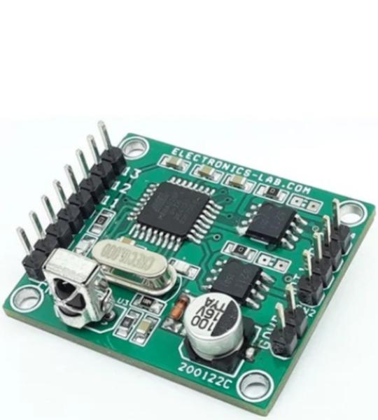
The Robot Controller is a very compact solution for controlling small and medium size robots using an Infrared remote. The project is fully Arduino compatible and consists of an ATMEGA328 microcontroller, 2 x BD6211 motor drivers, TSOP1838 IR sensor. BD6211 H-bridge is a full bridge driver for brush motor. The reference pin of BD6211 is pulled high and needs 2 x input to control the direction of the motor. 2 input pins of BD6211 are connected to ATMEGA328 for direction control of the motor. The project can be used to drive dual motors for 3-wheel robots or 4 x mini-DC motors. Input power supply 4.5V to 5.5V DC, the project can drive load up to 1A for each channel. Connector CN1 is provided to program the ATMEGA328 chips using Arduino IDE.
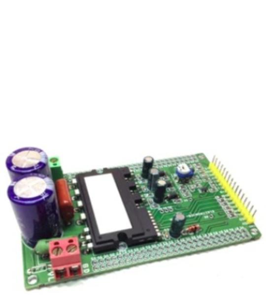
Intelligent Power Module (IPM) board has been designed using FSBS5CH60 IC from Fairchild, which provides a fully-featured, high-performance inverter output stage for AC Induction, BLDC, and PMSM motors. These modules integrate optimized gate drive of the built-in IGBTs to minimize EMI and losses, while also providing multiple on-module protection features including under-voltage lockouts, over-current shutdown, and fault reporting. The built-in, high-speed HVIC requires only a single supply voltage and translates the incoming logic-level gate inputs to the high-voltage, high-current drive signals required to properly drive the module’s internal IGBTs. Separate negative IGBT terminals are connected to the shunt resistor to provide the current feedback to the micro-controller. This IPM module helps to develop lots of power applications and also can be used as H-Bridge for brushed DC motor. The module mainly helps to drive Hall sensor-based or encoder-based motors, it doesn’t support the FOC algorithm, FOC-based IPM board is under development and will be published soon.
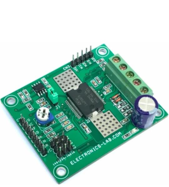
The project presented here is a 3-phase Brushless motor driver. The project consists of an L6235 device which is DMOS fully integrated 3-phase motor driver with overcurrent protection. Manufactured in BCD technology, the device combines isolated DMOS power transistors with CMOS and bipolar circuits on the same chip. The device includes all the circuitry needed to drive a 3-phase BLDC motor including a 3-phase DMOS bridge, a constant off-time PWM current controller, and the decoding logic for single-ended hall sensors that generates the required sequence for the power stage. Running the project in stand-alone mode, instead, three control pins enable the device, setting the direction of the rotation, breaking the motor, and the jumper chooses to run in torque or speed mode. The board is suitable for small motors used in many home appliances and can handle torque and speed control with a high efficiency of up to 95%.
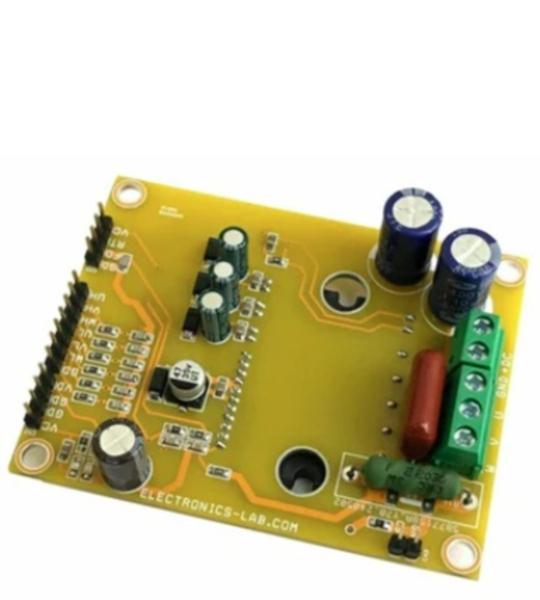
This is a Smart power module project designed for Small Power AC Motors. The FNB40560 chip is the heart of the project. A compact inverter project is ideal for small power motors such as fans and pumps. H-bridge configuration can also be created for low current high-voltage brushed DC motors. The Inverter project supports loads up to 5A. The DC power supply voltage is up to 400VDC. The project operates with 6 PWM signals. The parameters for bootstrap circuit elements are dependent on the PWM algorithm. For 5 kHz of switching frequency Bootstrap capacitors C2, C6, and C8 value is 33uF. Resistor R4, R5, R6, R12, R11, R8 and capacitor C9, C10, C11, C15, C16, C17 prevent improper signal due to surge-noise. ATS pin is provided to monitor the temperature of the IPM. A heatsink is needed for the IPM chip during operation or testing.
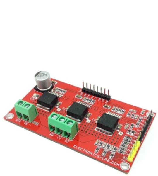
This BLDC motor driver board is equipped with a smart IFX007T half-bridge. The BLDC motor control project is capable to drive one BLDC motor. Alternatively, it can be used to drive one or two bi-directional DC motors (H-Bridge configuration, cascaded to support the second motor) or up to three uni-directional DC motors (half-bridge configuration). The implemented integrated IFX007T half-bridges can be controlled by a PWM via the IN Pin. Interfacing to a microcontroller or Arduino is easy by the integrated driver IC which features logic level inputs, diagnosis with current sense, slew rate adjustment, and dead time generation, etc. The three IFX007T half-bridges are also fully protected against over-temperature, under-voltage, overcurrent, and short circuit events. The project is capable of high-frequency PWM e.g., 30Khz. All inputs are logic level, current sense outputs are for diagnosis purposes, and slew rates are adjustable using R7, R8, R9. This is able to be used for fast and inexpensive prototyping of (BL)DC motor control, easy testing of half-and full-bridge motor control Status flag diagnosis with current sense capability, Over-temperature shut down with latch behavior and under-voltage shut down. It is advisable to use forced cool air to control the temperature of the IFX007 chip.
Cookie preferences