USD
USD INR
INR
Call Us Now
+91 9106756572
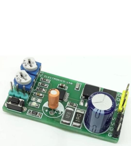
This is a power-saving pulse-width modulator (PWM) controller for solenoids with an internal supply regulator. The board is based on the DRV110 IC which is a PWM current controller which is specifically designed for solenoid and relay applications. The project regulates the current with a well-controlled waveform to reduce power dissipation on the load. The solenoid current is ramped up fast to ensure the opening of the valve or relay. After initial ramping, the solenoid current is kept at a peak value to ensure correct operation, after which the current is reduced to a lower hold level to avoid thermal problems and reduce power dissipation.
This is a power-saving pulse-width modulator (PWM) controller for solenoids with an internal supply regulator. The board is based on the DRV110 IC which is a PWM current controller which is specifically designed for solenoid and relay applications. The project regulates the current with a well-controlled waveform to reduce power dissipation on the load. The solenoid current is ramped up fast to ensure the opening of the valve or relay. After initial ramping, the solenoid current is kept at a peak value to ensure correct operation, after which the current is reduced to a lower hold level to avoid thermal problems and reduce power dissipation.
The peak current duration is set with an external capacitor C2. The peak and hold levels of the current ramp can be adjusted using trimmer potentiometer PR2 and PR1, as well as the PWM frequency, which can independently be set with external resistor R6. External setting resistors can also be omitted if the default values for the corresponding parameters are suitable for the application. The DRV110 device has an internal Zener diode that limits the supply at VIN to VZENER for applications that require a higher supply voltage. High DC voltages such as 48V can also be accommodated this way.
Enable and disable the switch is controlled by the EN pin. The EN pin contains an internal resistor network to set the pin to logic HIGH when the EN pin is floating. This feature can be used for situations where a control signal is not required and the solenoid is only energized when a supply voltage is present. Such applications could be valves or contactors. By pulling down Enable pin disable the output.
IPEAK and IHOLD depend on PR1 and PR2 trimmer pot resistance values RPEAK-PR1 and RHOLD-PR2 as shown in the circuit. If the PEAK pin or HOLD pin is connected to the ground or RPEAK or RHOLD is less than 43.33 kΩ (typical), then IPEAK is at its default value of 300 mA for IPEAK and 50 mA for IHOLD.
The IPEAK value can alternatively be set using trimmer pot PR1. For example, if a PR1 60-kΩ (= RPEAK) is connected between PEAK and GND, and RSENSE = 1 Ω, then the externally set IPEAK level will be 900 mA. If RPEAK -PR1 = 200 kΩ and RSENSE = 1 Ω, then the externally set IPEAK level will be 300 mA. It is not recommended to use a resistor between 30 kΩ and 55 kΩ to avoid the IPEAK or IHOLD current slipping from the maximum current setting to the default setting. In case RSENSE = 2 Ω instead of 1 Ω, then IPEAK = 450 mA (when RPEAK-PR1 = 55 kΩ) and IPEAK = 150 mA (when RPEAK-PR1 = 200 kΩ
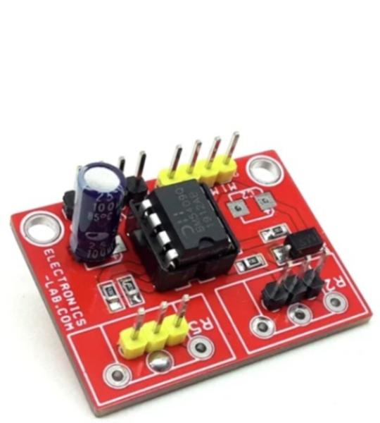
This is a low-cost position control closed-loop analog-servo using brushed DC motor and potentiometer as feedback. This product provides all necessary active functions for a closed-loop servo system using a Brushed DC Motor and potentiometer mounted on the output shaft of the DC Motor with Gear. The module is ideally suited for almost any servo positioning application. Can be used in applications such as side mirror movement control for cars, car head lamp beam control, animatronics, robotics, etc.
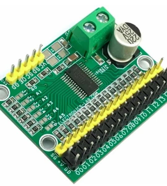
This is a 16-channel servo driver that can drive 16 x RC servos over I2C interface. The project is built using PCA9685 chip, a 16-channel PWM generator that can drive 16-channel servos simultaneously. The board can be connected to Arduino or another microcontroller. Driving robots, and animatronics puppets is easy with this board. The board works with 5VDC and a separate power supply connector is provided to power the RC servo with 6VDC. 6 x address Solder jumper is provided to set the board address, and this helps users to wire up 62 board on a single I2C line and drive up to 992 servos. The board also can be used for other applications that require 16-channel PWM signals. The frequency can be adjusted between 24 Hz to 1526 Hz and the duty cycle ranges from 0 to 100%.
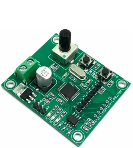
This is an RC servo controller board that allows users to record RC servo motor movement and playback it back with precision. There is an onboard potentiometer to control the RC servo up to 180 degrees. It allows you to record the movement of one servo, a few seconds in duration. Servo movement can be mimicked using the onboard potentiometer. Servo movement data is stored onboard the EEPROM memory chip. The project is Arduino compatible and can be modified to work as a data logger and other applications that require EEPROM and SD Card data logs.
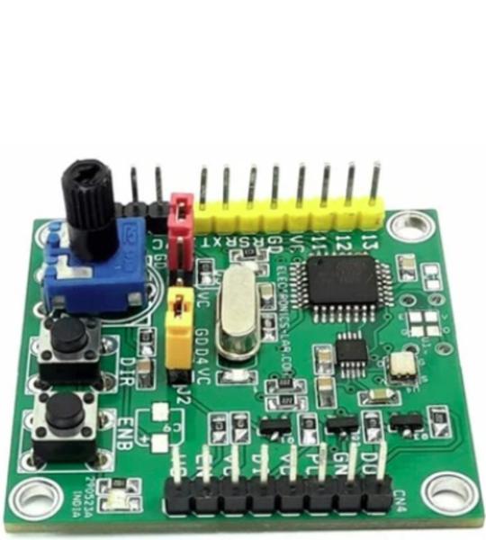
A programmable pulse generator is a very useful tool for stepper, BLDC, and AC servo drivers. Various stepper and servo drivers work with step and direction inputs. This project is the right solution to drive such drivers since it can provide a high-frequency output which is important for most AC servo drivers. The project provides a jitter-free high-frequency pulse, direction, and enable signal. The output frequency can be configured up to 12 MHz since the project is Arduino-compatible. All outputs are open collector types (5V). 2 x tactile switches are provided to set the direction and enable. An onboard trimmer potentiometer is provided to adjust the step frequency.
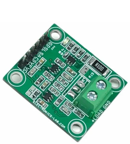
This is an I2C electronic load, intended for testing power supplies, solar panels, batteries, and supercapacitors. The board consists of an I2C interface DAC MCP4725, OPAMP U2 acts as V to I (Voltage to Current), OPAMP U3 measures the load current across the shunt resistor and provides 0 to 4.9V Voltage with a current range of 0 to 1A. Users may control the battery discharge current using the MCP4725 DAC in the range 0 to 1A. The circuit also provides load current feedback and voltage feedback. This way it can help users to measure the battery’s performance. Suppose the user desires to measure the battery’s performance as it is being discharged at constant power. In that case, a current measuring circuit can be used in the feedback loop to enforce the constant power constraint. This enables you to discharge a battery at a controlled way. The project can handle 1A @ 24V, thus a total of 24W with the use of a large-size heatsink and fan. The circuit works with 5V DC voltage input. The project can be used with Arduino, ESP32, or other microcontroller.
Cookie preferences