USD
USD INR
INR
Call Us Now
+91 9106756572
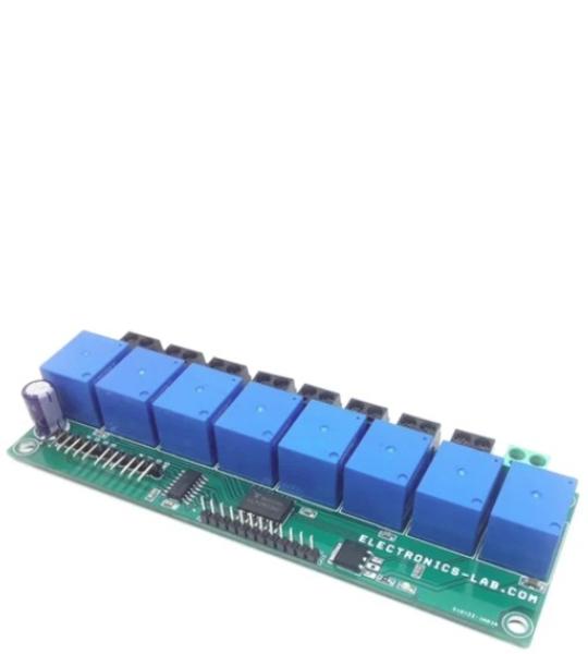
This is an SPI Interface multichannel relay board for high voltage AC or low voltage DC loads. It is ideal for controlling LEDs lights, coffee machines, fans, pumps, or other high-voltage electrical appliances. The board also breaks out the SPI header, so controlling other boards is still possible. Each relay can handle current up to 7A @ 250V AC/30V DC. This 8 x channel board is mainly designed for AC loads, but it can also drive DC loads, screw terminals on each channel enable the easy interface of the AC load, and each point is marked as AC-Live and AC Neutral. Refer to the connection diagram for the interface. The project consists of 8 x 12V relays with load capacity 7A @ 250V AC, ULN2803 8 channel relay driver, 74HC595 SPI to 8 output, 5V regulator 7805, power LED, screw terminals for loads and AC input, header connector for SPI input and output.
This is an SPI Interface multichannel relay board for high voltage AC or low voltage DC loads. It is ideal for controlling LEDs lights, coffee machines, fans, pumps, or other high-voltage electrical appliances. The board also breaks out the SPI header, so controlling other boards is still possible. Each relay can handle current up to 7A @ 250V AC/30V DC. This 8 x channel board is mainly designed for AC loads, but it can also drive DC loads, screw terminals on each channel enable the easy interface of the AC load, and each point is marked as AC-Live and AC Neutral. Refer to the connection diagram for the interface. The project consists of 8 x 12V relays with load capacity 7A @ 250V AC, ULN2803 8 channel relay driver, 74HC595 SPI to 8 output, 5V regulator 7805, power LED, screw terminals for loads and AC input, header connector for SPI input and output.
SPI Interface: 6-pin header CN11 is provided for data input and CN10 connector is the SPI output that can be interfaced with multiple boards.
We have created and tested a large-size 7-segment display with this board and an Arduino. Arduino example code is available as a download. Wiring between Arduino vs SPI 8 channel board as follows:
Arduino Code Credits: http://www.learnerswings.com
Each segment is made using 20W LED Batten (LED Tube Light) with Dimensions 113.5 x 2.8 x 6.8 cm, which works with 230V AC supply, user may use a smaller batten.
The project is tested with a single 7-segment display, but the user may use multiple displays with multiple boards, and use SPI outputs for other boards.
Connections for 7 Segments + DP
SPI In CN11 Connections
SPI Output CN10 Connections
AC 230V Input CN1
AC Loads – 8 Channel (CN2, CN3, CN4, CN5, CN6, CN7, CN8, CN9)
Connector CN13
Power Supply Input – CN12
Connector CN12 (Optional Connector, do not Install read Note 1 for more info)
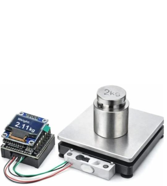
This compact shield is based on the HX711 ADC, specifically designed to interface load cells and strain gauge sensors. It can be paired with the OLEDUINO-V2, enabling the creation of a miniature electronic weighing scale.
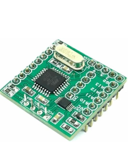
This board consists of Arduino-compatible hardware which includes an OLED display, ADS1115 4-Channel 16Bit ADC, Arduino-compatible Microcontroller ATMEGA328, a connector for Arduino Programming, a connector for 4 Channel Analog input, and a connector for a couple of I/O lines. Operating supply 5V DC.
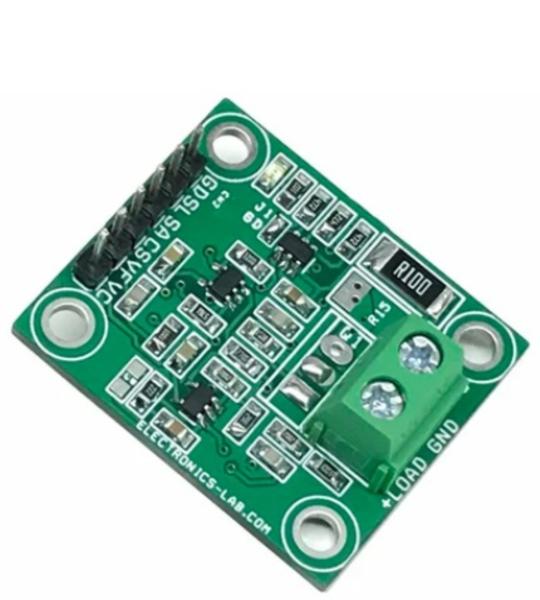
This is an I2C electronic load, intended for testing power supplies, solar panels, batteries, and supercapacitors. The board consists of an I2C interface DAC MCP4725, OPAMP U2 acts as V to I (Voltage to Current), OPAMP U3 measures the load current across the shunt resistor and provides 0 to 4.9V Voltage with a current range of 0 to 1A. Users may control the battery discharge current using the MCP4725 DAC in the range 0 to 1A. The circuit also provides load current feedback and voltage feedback. This way it can help users to measure the battery’s performance. Suppose the user desires to measure the battery’s performance as it is being discharged at constant power. In that case, a current measuring circuit can be used in the feedback loop to enforce the constant power constraint. This enables you to discharge a battery at a controlled way. The project can handle 1A @ 24V, thus a total of 24W with the use of a large-size heatsink and fan. The circuit works with 5V DC voltage input. The project can be used with Arduino, ESP32, or other microcontroller.
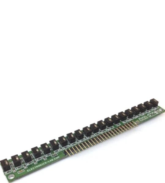
Product consists of 20 non-contact infrared reflective sensors and each sensor provides an analog output. QRD114 sensor is the heart of the project which includes Infrared LED and photosensor. The output of each sensor is high and goes low as objects or lines detected. The analog output voltage is proportional to IR reflected back to the sensor. The project has been designed to be used in robotics applications for line follower or multi-object sensor. Sensor requires 5V DC to work, all LEDs have current limiting resistors, each output has a pull resistor, and the normal output of each sensor is high due to the pull-up resistor and goes low as object or line is detected. IR LEDs power ON/OFF can be controlled using Q1 BD140 PNP BJT transistor which requires a low voltage for normal operation or all IR LED and can be powered up to 5V DC with help of VL input pin. Two 3mm mountings provided for easy mounting on robot chassis. By reflected infrared light, it can detect transitions from light to dark or any objected comes across the sensor.
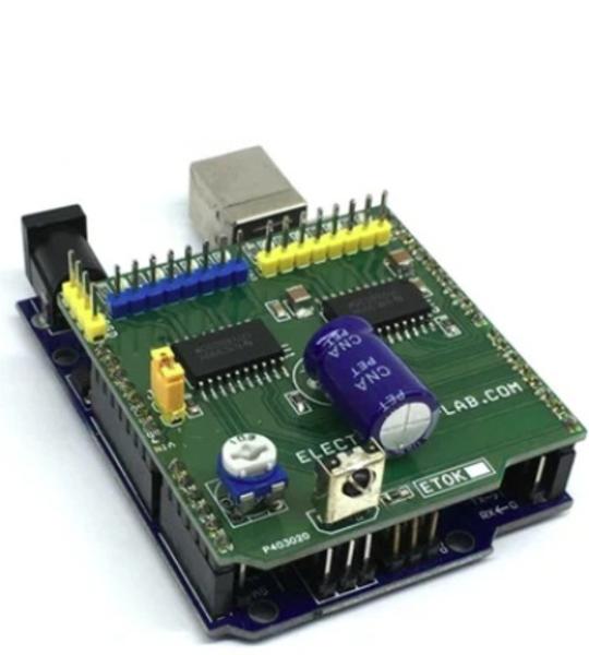
The 8 Channel Driver Arduino UNO Shield is designed to enable users to switch inductive loads for up to 800mA each channel and up to 24V DC with no heat-sink needed. It is ideal for such applications as driving 2x unipolar stepper motors, solenoids, relays, and small DC motors. It uses 2x DRV8803 Chip from Texas instruments which is 4 channel low side driver with over current protection. IC’s Internal shutdown protection function is provided for overcurrent protection, short circuit protection, under-voltage lockout, and over temperature. Faults are indicated by a fault output pin that is normally high and goes low if a fault condition occurs. Reset and enable pins has internal pull-down resistors.
Cookie preferences