USD
USD INR
INR
Call Us Now
+91 9106756572
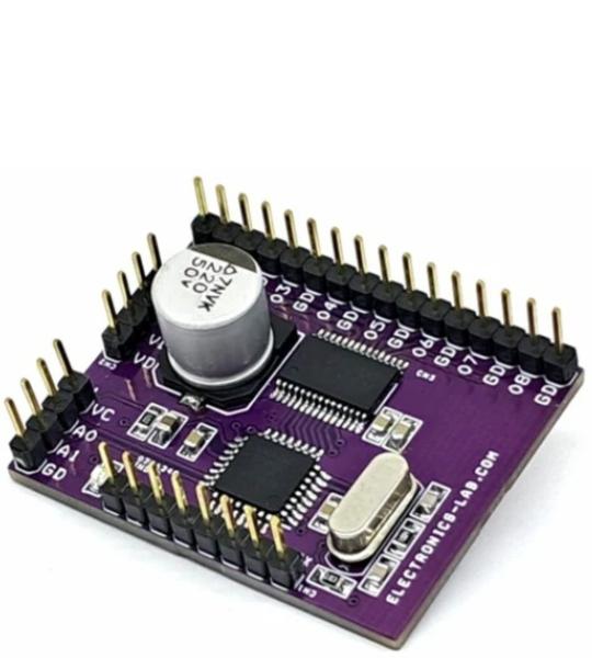
The project presented here is a high-side switch (8 channels) with MOSFET output. The Arduino board consists of an Arduino-compatible microcontroller ATMEGA328 and TPD2015FN – 8 Channels MOSFET switch. All 8 inputs of TPD2015FN are TTL compatible. The project is suitable for driving inductive and resistive loads such as industrial programmable logic controllers, motors, and lamps in factory automation equipment, etc. This product has built-in overcurrent and over-temperature protection functions, which contribute to improved stability of the system.
The project presented here is a high-side switch (8 channels) with MOSFET output. The Arduino board consists of an Arduino-compatible microcontroller ATMEGA328 and TPD2015FN – 8 Channels MOSFET switch. All 8 inputs of TPD2015FN are TTL compatible. The project is suitable for driving inductive and resistive loads such as industrial programmable logic controllers, motors, and lamps in factory automation equipment, etc. This product has built-in overcurrent and over-temperature protection functions, which contribute to improved stability of the system.
TPD2015FN is a high-side switch (8-channels) with MOSFET outputs. This is the monolithic power IC that can be driven directly from CMOS, TTL logic circuitry (MCU, etc.) and has over-current and over-temperature protection features.
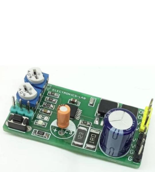
This is a power-saving pulse-width modulator (PWM) controller for solenoids with an internal supply regulator. The board is based on the DRV110 IC which is a PWM current controller which is specifically designed for solenoid and relay applications. The project regulates the current with a well-controlled waveform to reduce power dissipation on the load. The solenoid current is ramped up fast to ensure the opening of the valve or relay. After initial ramping, the solenoid current is kept at a peak value to ensure correct operation, after which the current is reduced to a lower hold level to avoid thermal problems and reduce power dissipation.
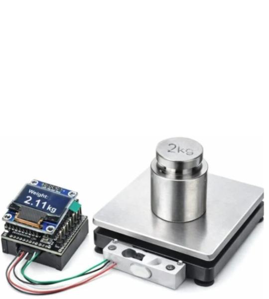
This compact shield is based on the HX711 ADC, specifically designed to interface load cells and strain gauge sensors. It can be paired with the OLEDUINO-V2, enabling the creation of a miniature electronic weighing scale.
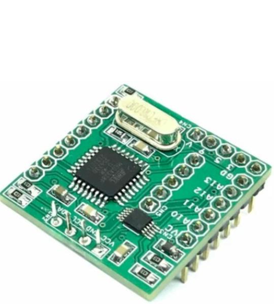
This board consists of Arduino-compatible hardware which includes an OLED display, ADS1115 4-Channel 16Bit ADC, Arduino-compatible Microcontroller ATMEGA328, a connector for Arduino Programming, a connector for 4 Channel Analog input, and a connector for a couple of I/O lines. Operating supply 5V DC.
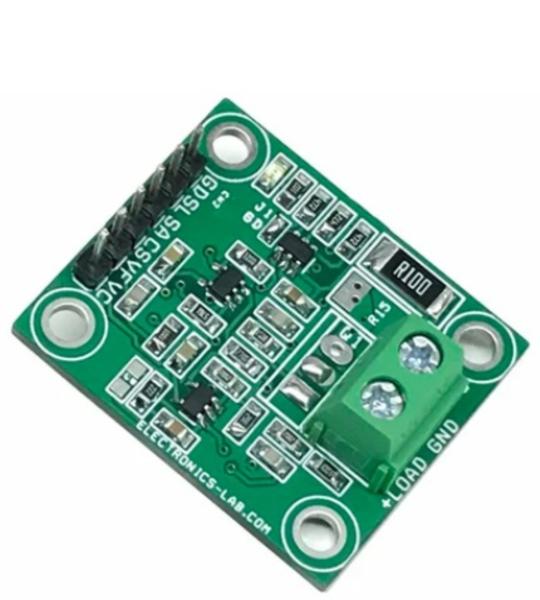
This is an I2C electronic load, intended for testing power supplies, solar panels, batteries, and supercapacitors. The board consists of an I2C interface DAC MCP4725, OPAMP U2 acts as V to I (Voltage to Current), OPAMP U3 measures the load current across the shunt resistor and provides 0 to 4.9V Voltage with a current range of 0 to 1A. Users may control the battery discharge current using the MCP4725 DAC in the range 0 to 1A. The circuit also provides load current feedback and voltage feedback. This way it can help users to measure the battery’s performance. Suppose the user desires to measure the battery’s performance as it is being discharged at constant power. In that case, a current measuring circuit can be used in the feedback loop to enforce the constant power constraint. This enables you to discharge a battery at a controlled way. The project can handle 1A @ 24V, thus a total of 24W with the use of a large-size heatsink and fan. The circuit works with 5V DC voltage input. The project can be used with Arduino, ESP32, or other microcontroller.
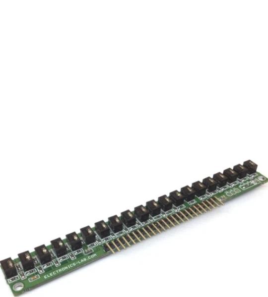
Product consists of 20 non-contact infrared reflective sensors and each sensor provides an analog output. QRD114 sensor is the heart of the project which includes Infrared LED and photosensor. The output of each sensor is high and goes low as objects or lines detected. The analog output voltage is proportional to IR reflected back to the sensor. The project has been designed to be used in robotics applications for line follower or multi-object sensor. Sensor requires 5V DC to work, all LEDs have current limiting resistors, each output has a pull resistor, and the normal output of each sensor is high due to the pull-up resistor and goes low as object or line is detected. IR LEDs power ON/OFF can be controlled using Q1 BD140 PNP BJT transistor which requires a low voltage for normal operation or all IR LED and can be powered up to 5V DC with help of VL input pin. Two 3mm mountings provided for easy mounting on robot chassis. By reflected infrared light, it can detect transitions from light to dark or any objected comes across the sensor.
Cookie preferences