USD
USD INR
INR
Call Us Now
+91 9106756572
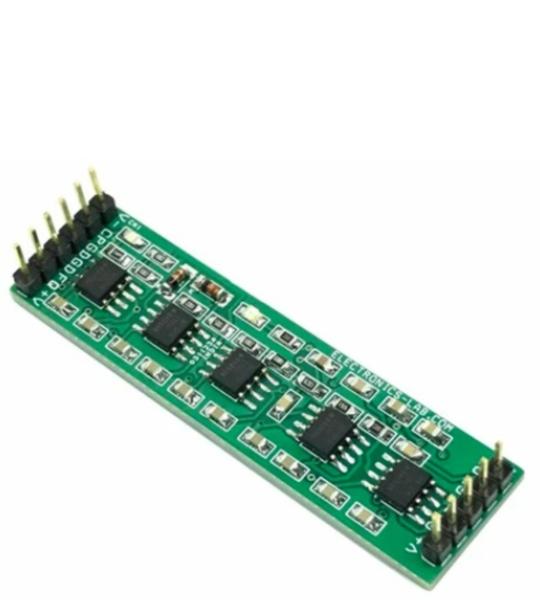
This is a simple signal conditioner circuit for Piezoelectric sensors. The circuit converts the input charge to voltage and the level shifts to the ADC input range of 0.1 V to 2.4 V. The circuit is built using AD8608 OPAMP from Analog devices. Piezoelectric elements are used to construct transducers for a vast number of different applications. Piezoelectric materials generate an electrical charge in response to mechanical movement, or vice versa, produce mechanical movement in response to electrical input. The board shown here is suitable for the Kistler type 8002K sensor. The K8002K is a high-precision accelerometer for shock and vibration measurements.
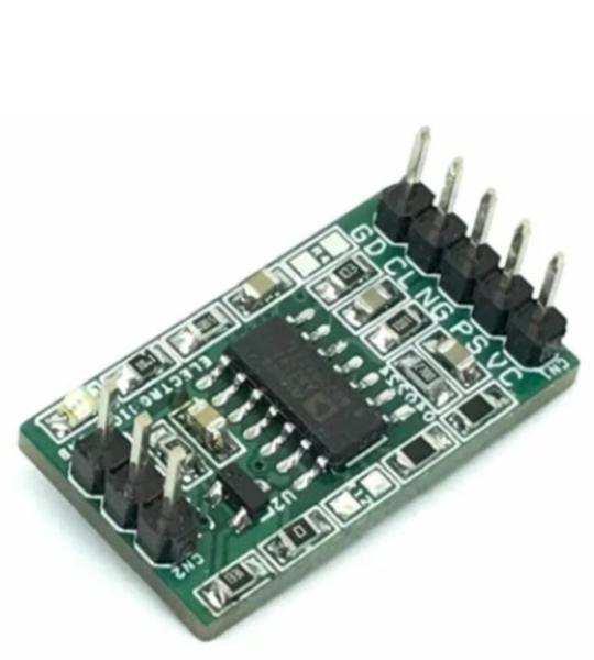
The module presented here is a sensor signal conditioner based on ZSC31010 CMOS integrated circuit, which enables easy and precise calibration of resistive bridge sensors via EEPROM programming. When mated to a resistive bridge sensor, it will digitally calibrate offset and gain with the option to calibrate offset and gain coefficients and linearity over temperature. A second-order compensation can be enabled for temperature coefficients of gain or offset or bridge linearity. ZSC31010 module communicates via IDT’s ZACwire serial interface to the host computer and it is easily mass-calibrated in a Windows environment. Once calibrated, the output signal pin can provide selectable 0 to 1 V absolute analog output; rail-to-rail ratiometric analog output; or digital serial output of bridge data with optional temperature data. U1 LM317 provides the 5V DC to the sensor chip. D1 is the power LED.
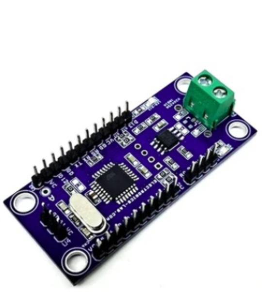
The RS-485 Linear Hall Sensor Interface Board is an Arduino-compatible module built around an ATmega328 microcontroller. It combines two Texas Instruments products: a SN65HVD08DR half-duplex RS-485 transceiver with a DRV5053 linear Hall-effect sensor on a single board. This creates a self-contained node that measures magnetic fields and reports data over an industrial RS-485 network.
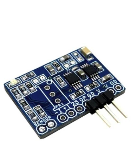
This is a new project, a single supply instrumentation amplifier with onboard bridge configuration, and a 2.5V precision reference voltage chip. The project can be configured for applications such as thermocouple amplifier, bridge amplifier, ECG amplifier, pressure sensors, medical instrumentation, portable instrumentation, RTD sensor amplifier. The project is based on INA333 micropower, zero drift, rail to rail out instrumentation amplifier chip. REF5025AID chip provides a precise 2.5V reference voltage. The board can be configured as an instrumentation amplifier or as a strain gauge amplifier with few easy changes.
The project presented here is an analog capacitive humidity sensor converter board suitable for various humidity measurement tasks. The circuit comes from Texas Instruments application note (see below). Most conventional capacitive proximity sensors produce a digital signal, but this circuit produces a DC output voltage that is a function of the relative humidity of the environment. The oscillator input for this circuit is a 1Khz sine source (1Vpp) feed to FQ input. The low frequency and sine characteristics keep RFI problems at a minimum. This sensor output converter may prove difficult to construct because of the small capacitances involved, parasitic capacitances in the sensor circuit, and noise pickup. The circuit requires an external 1Khz sinewave with 1Vpp signal and operates with a dual 15V DC supply.
This product offers a dual−channel low component count interface solution for ground-referenced variable reluctance sensors. Each of the two identical channels interfaces with a variable−reluctance sensor, and continuously compares the sensor output signal to a user−programmable internal reference. An alternating input signal of appropriate amplitude at IN1 or IN2 will result in a rectangular waveform at the corresponding OUT1 and OUT2 terminal, suitable for interface to either standard microprocessors or standard logic families. A diagnostic input, common to both channels, provides a means to test for degradation or loss of the physical connector to both sensors. Each channel of the circuit has independent input bias and clamp circuitry, and independent comparators with Hysteresis voltage generators. Both channels share a common reference generator for normal and diagnostic modes. Basically, the circuit converts the sinewave signal of the sensor into a clean rectangular wave signal.
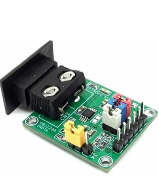
This Thermocouple Amplifier project provides a simple, low-cost solution for measuring thermocouple temperature. This board simplifies many of the difficulties of measuring thermocouples output. An integrated temperature sensor performs cold junction compensation. A fixed-gain instrumentation amplifier amplifies the small thermocouple voltage to provide a 5 mV/°C output. The high common-mode rejection of the amplifier blocks common-mode noise that the long thermocouple leads can pick up. For additional protection, the high impedance inputs of the amplifier make it easy to add extra filtering. The module can be used as standalone thermometers or as switched output setpoint controllers using either a fixed or remote setpoint control. The module can be powered from a single-ended supply (less than 3V) and can measure temperatures below 0°C by offsetting the reference input. To minimize self-heating, an unloaded AD8495 typically operates with a total supply current of 180 μA, but it is also capable of delivering in excess of ±5 mA to a load. The board can be interfaced with K-type (chromel-alumel) thermocouples. With an operating single supply of 5V, the 5 mV/°C output allows the devices to cover nearly 1000 degrees of a thermocouple’s temperature range. The project can also work with 3V supplies, allowing them to interface directly with lower-supply ADCs. They can also work with supplies as large as 36V in industrial systems that require a wide common-mode input range. The AD8495 cold junction compensation is optimized for operation in a lab environment, where the ambient temperature is around 25°C. The AD8495 is specified for an ambient range of 0°C to 50°C.
This product can be used in bidirectional high-voltage measurements. The output is fully isolated from the input side and can be used for applications such as high-voltage DC-DC converters, High-Voltage EV chargers, SMPS, 3 Phase motor drivers, inverters, etc. The board is built using the AMC3330 chip. This chip is a precision, isolated amplifier with a fully integrated, isolated DC/DC converter that allows single-supply operation from the low side of the device. The reinforced capacitive isolation barrier is certified according to VDE V 0884-11 and UL1577 and separates sections of the system that operate on different common-mode voltage levels and protect low-voltage domains from damage. The circuit senses high voltage in the range from -1V to 1V across resistor dividers R11, R4, R5, R8, and R12 and provides differential analog output Out-P and Out-N. The integrated isolated DC/DC converter allows the measurement of non-ground-referenced signals.
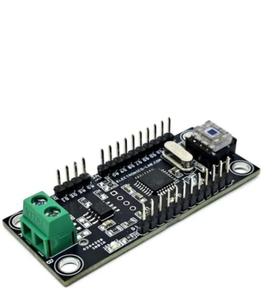
This Arduino-compatible hardware is primarily designed for RS485-based applications. It features an ATmega328 microcontroller, RS485 SN65HVD485E Half-Duplex RS-485 Transceiver chip, OPT101 light sensor, multiple I/O lines, and a provision for mounting a 0.96-inch OLED display.
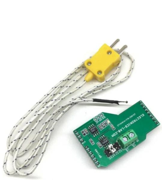
This is a Type K Thermocouple Sensor Amplifier Arduino Shield that enables an Arduino board to acquire temperatures from a thermocouple of type K. The shield works with a single supply and takes 5V DC from the Arduino board, the output of the circuit is 0 to 4V DC for 0-degree centigrade to 400C. The output of the amplifier is connected to the A0 analog pin of Arduino. A typical application of thermocouples is in boilers, soldering stations, and heaters. Also, 3D printers rely on thermocouples to measure the extruder temperature.
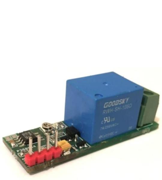
This project simply switches the system OFF or ON whenever the temperature rises at the desired set point. The desired setpoint can be set using a fixed resistor R6 or PR1 trimmer potentiometer. Use any of at a time R6 or PR1. You can calculate the setpoint resistor R6 using the following equation:
Cookie preferences