USD
USD INR
INR
Call Us Now
+91 9106756572
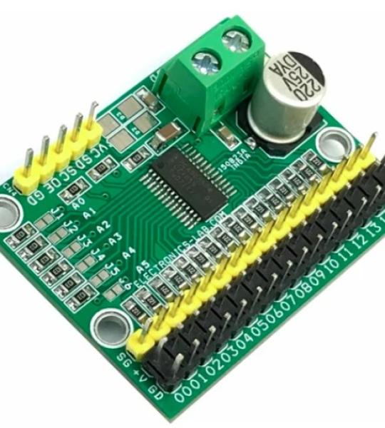
This is a 16-channel servo driver that can drive 16 x RC servos over I2C interface. The project is built using PCA9685 chip, a 16-channel PWM generator that can drive 16-channel servos simultaneously. The board can be connected to Arduino or another microcontroller. Driving robots, and animatronics puppets is easy with this board. The board works with 5VDC and a separate power supply connector is provided to power the RC servo with 6VDC. 6 x address Solder jumper is provided to set the board address, and this helps users to wire up 62 board on a single I2C line and drive up to 992 servos. The board also can be used for other applications that require 16-channel PWM signals. The frequency can be adjusted between 24 Hz to 1526 Hz and the duty cycle ranges from 0 to 100%.
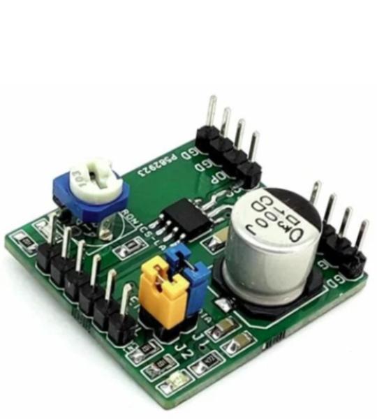
This Half-bridge module provides current measurement and regulation features for various loads. The module can be used to drive solenoids, Relays, Valves, DC-DC converters, Brushed DC motors, or other loads. It can operate from a 5V to 55V supply voltage and can deliver up to 3A of output current (depending on ambient temperature). Cycle-by-cycle current regulation, current limiting is adjustable using PR1 trimmer pot. Internal diagnostic and protection features include open-load detection, over-current protection (OCP), under-voltage lockout (UVLO), and thermal shutdown. The overcurrent limit is set to 3A and the retry time is 1.6mS. Solenoids can be controlled ON/OFF using Jumper J1. Use the PWM signal at the input pin for DC motor speed control.
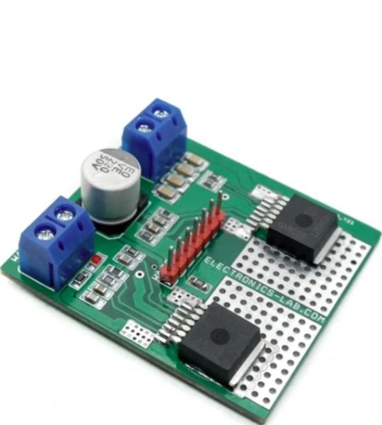
This motor driver circuit can drive a brushed DC motor with up to 250W of continuous load. The project can be controlled with the general logic IO-Ports of any microcontroller. Either an Arduino Uno or other microcontroller can be used as the control board. The project uses two IFX007T IC from Infineon. Each IC provides half-bridge operation featuring one P-channel high side MOSFET and one N-channel low side MOSFET with an integrated driver IC. The IFX007T half-bridge is easy to control by applying logic level signals to the IN and INH pin. When applying a PWM to the IN pin the current provided to the motor can be controlled with the duty cycle of the PWM. With external R6, R9 resistors connected between the SR pin and GND you can set the slew rate of the power switches. The Motor Control board can be easily connected to any Arduino board or microcontroller via headers.
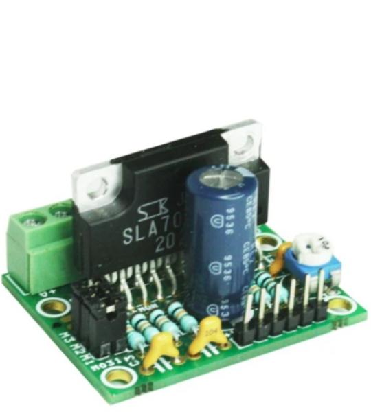
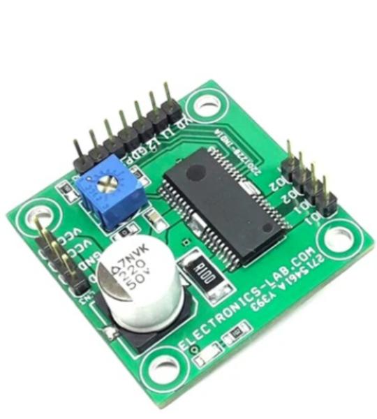
This tiny Unipolar stepper motor driver has been designed around SLA7078MPR IC from Sanken. It is a unipolar stepper Motor driver that can handle current up to 3 Amps and has micro-stepping up to 1/16 steps. On-board Jumpers are available to set the Micro-stepping and Preset (Potentiometer) to set the current.
The SLA7078MPR series motor driver ICs features unipolar drivers. The clock-in type input interface allows simplified control logic, and options for built-in sense current detection and load circuit short or open protection (patent pending) provide lower loss, and lower thermal resistance.
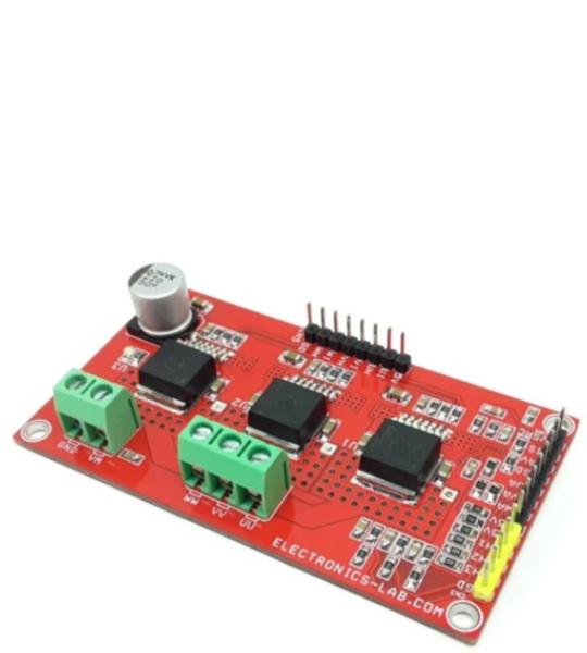
This BLDC motor driver board is equipped with a smart IFX007T half-bridge. The BLDC motor control project is capable to drive one BLDC motor. Alternatively, it can be used to drive one or two bi-directional DC motors (H-Bridge configuration, cascaded to support the second motor) or up to three uni-directional DC motors (half-bridge configuration). The implemented integrated IFX007T half-bridges can be controlled by a PWM via the IN Pin. Interfacing to a microcontroller or Arduino is easy by the integrated driver IC which features logic level inputs, diagnosis with current sense, slew rate adjustment, and dead time generation, etc. The three IFX007T half-bridges are also fully protected against over-temperature, under-voltage, overcurrent, and short circuit events. The project is capable of high-frequency PWM e.g., 30Khz. All inputs are logic level, current sense outputs are for diagnosis purposes, and slew rates are adjustable using R7, R8, R9. This is able to be used for fast and inexpensive prototyping of (BL)DC motor control, easy testing of half-and full-bridge motor control Status flag diagnosis with current sense capability, Over-temperature shut down with latch behavior and under-voltage shut down. It is advisable to use forced cool air to control the temperature of the IFX007 chip.
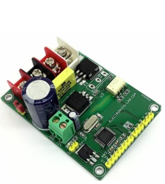
This is a Brushed DC motor controller designed to control one brushed DC motor up to 5A. It can control the speed of the DC motor using a Radio Control (RC) System. This Arduino compatible hardware converts RC PWM signal into 0 to 100% duty cycle PWM which further drives high current load using MOSFET. The project consists of an Atmega328 microcontroller, and a gate driver optocoupler provides isolation between MOSFET and microcontroller circuit to prevent high voltage and noise traveling from the motor and related circuit to the microcontroller. The circuit can drive a motor up to 5A with a power supply of 12V to 40V DC. The board has the option to mount higher voltage and current MOSFET, which can drive higher Voltage and current load. In this case don’t install Q2, install Q1 MOSFET FDH3632, and replace diode D2 with a higher current diode.
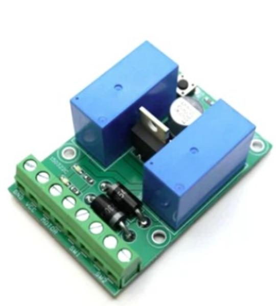
The module described here is a very useful device for use with linear actuators. This controller prevents the actuator from reaching the physical movement limits of the actuator, thus it prevents burnout of motor and physical/mechanical damage to the actuator itself to the mechanical machine associated with it. It also allows for a smoother stopping motion once the end of travel is reached. The project is capable of driving DC brushed motors up to 3A, it supports 12V DC or 24V DC motors with few changes. Two limit switches are used on both sides of the actuator. The limit switches are available with 2 contacts normally open and normally closed. It is advisable to use normally closed contacts. The project consists of 2 DPDT relays, two 1N5402 diodes, Power LED, Motor direction LEDs, 2 x tactile switches, DC supply capacitor, screw terminals, etc.
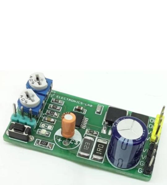
This is a power-saving pulse-width modulator (PWM) controller for solenoids with an internal supply regulator. The board is based on the DRV110 IC which is a PWM current controller which is specifically designed for solenoid and relay applications. The project regulates the current with a well-controlled waveform to reduce power dissipation on the load. The solenoid current is ramped up fast to ensure the opening of the valve or relay. After initial ramping, the solenoid current is kept at a peak value to ensure correct operation, after which the current is reduced to a lower hold level to avoid thermal problems and reduce power dissipation.
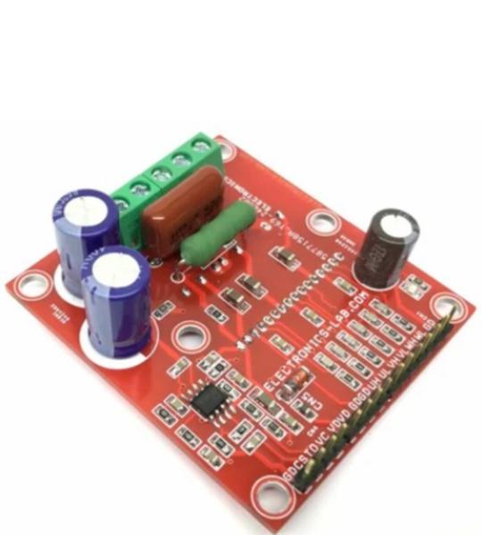
This is a powerful yet small size low profile brushed DC motor drive system with a few key features like adjustable constant current control, direction control, brake controls, Alert output, PWM for speed control etc. BD63130AFM chip is the heart of the project which is an H-bridge motor driver for the DC brush motor. This driver can facilitate low power consumption by direct PWM or PWM constant current control. There are various built-in protection circuits in this IC. It is possible to output an abnormal detection signal for Wired-OR that notifies each protection circuit operation, and this contributes to set high reliability.
This is an advanced Motion module providing a fully featured, high-performance inverter output stage for AC induction, BLDC and PMSM motors such as refrigerators, fans, and pumps. This module is based on NFA50460 chip which integrates the optimized gate drive of the built−in IGBTs (FS4 RC IGBT technology) to minimize EMI and losses, while also providing multiple on−module protection features including under−voltage lockouts and thermal monitoring. The built−in high-speed Driver IC requires only a single supply voltage and translates the incoming logic−level gate inputs to the high voltage, high current drive signals required to properly drive the module’s internal IGBTs. Separate open emitter IGBT terminals are available for each phase to support the widest variety of control algorithms. Heatsink is a must for the IC before conducting any test.
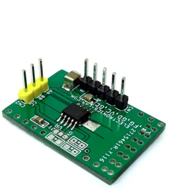
Driving a 3-phase brushless DC motor is very easy with this product. It is a simple and easy-to-build project that requires only a few external components. The circuit is based on AMT49400 IC which is an advanced 3-phase, Sensorless, brushless DC (BLDC) motor driver with integrated power MOSFETs. The chip includes the field-oriented control (FOC) algorithm which is fully integrated to achieve the best efficiency and acoustic noise performance. The motor speed is controlled by applying a duty cycle signal to the PWM input. Users may use Arduino, microcontroller, or discrete circuit to generate PWM for the speed controller. It is a hassle-free easy to use board, just connect the 3 phase brushless motor, connect the power supply and feed PWM to control the speed of the motor. This project is the best choice to drive a FAN motor, small pumps, and brushless toy motors, etc. The circuit also outputs FG speed output information which can be used for feedback. Chip also has a short circuit protection feature that prevents damage to the IC or motor. Any of these three conditions: phase to GND, phase to VBB, and phase to phase will trigger the OCP event, and the AMT49400 will stop supplying current to the motor immediately. The OCP can recover after a power cycle or PWM demand cycle. If the OCP restart mode (EEPROM setting) is “time”, the OCP can recover after 5 seconds.
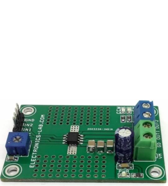
The highly efficient DC brushed motor driver including an onboard shunt resistor for current regulation presented here is built using the DRV8251 chip. The operating supply voltage range of the project is 4.5V to 48V DC and the default output current capability is 2.1A. A trimmer potentiometer PR1 is provided to adjust the current regulation threshold. The device includes under-voltage lockout (UVLO), Latched overcurrent protection (OCP), and thermal shutdown (TSD). Output is disabled and latched when over current/stall current condition occurs. For direction control of the motor use IN1 and IN2 as logic inputs and for speed control these inputs can be connected to a PWM source with duty cycle 0 to 100% and frequency 20Khz.
Cookie preferences