USD
USD INR
INR
Call Us Now
+91 9106756572
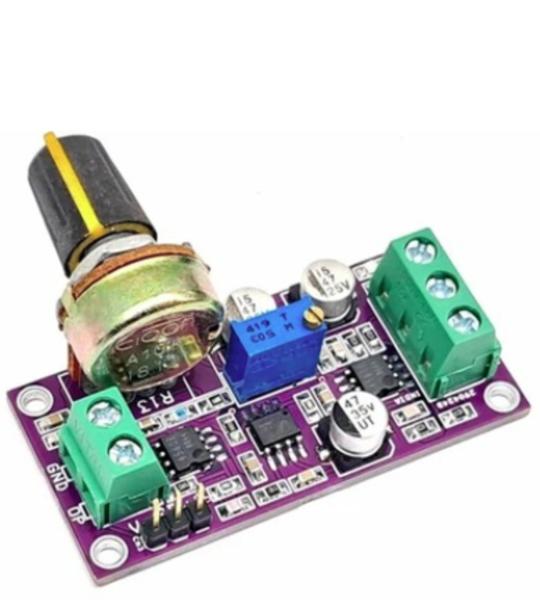
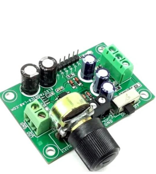
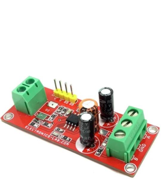
The project presented here is a Voltage Controlled Amplifier (VCA). A VCA board helps users control the audio level from a remote potentiometer. This board requires a balanced audio signal. Gain control voltage can be adjusted through potentiometer R13. The project works with a dual (±15V) power supply. Screw terminal connectors are provided for signal input and signal output. The project is built using THAT2181LA chip which is a VCA, designed for high performance in audio-frequency applications requiring exponential gain control, low distortion, wide dynamic range, and low control-voltage feedthrough. This chip controls the gain by converting an input current signal to a bipolar logged voltage, adding a DC control voltage, and re-converting the summed voltage back to a current through a bipolar antilog circuit. Stereo control of VCA with a single potentiometer is possible.
Many high-performance audio digital-to-analog converters (DACs) feature a current output that must be converted into a voltage output for use with audio amplifiers. In premium automotive audio applications, for example, it is critical that the DAC signal-to-noise ratio (SNR) and total harmonic distortion plus noise (THD+N) performance is not compromised by the current-to-voltage (I-V) output stage. The first stage of the circuit converts the current output to a voltage output by providing a virtual ground potential to the OUTP and OUTN nodes of the DAC. The current flowing from the DAC then creates a voltage across the resistor, R4, R18, in the feedback loop. Note that current-output audio DACs have a common mode current that creates an offset to confirm that the DAC is always sourcing current. This common-mode current also results in the output of the first stage always being a negative value. The supplies of the amplifiers of the circuit are not required to be symmetrical. The second stage of the circuit is a differential amplifier that converts the differential voltage of the first stage into a single-ended output voltage. In the third-order, low-pass filter (LPF) circuit, the output level of 2.1 V RMS and 123-dB signal-to noise ratio is achieved. A NE5534 operational amplifier is used for the I/V circuit to obtain the specified performance. Dynamic performance such as the gain bandwidth, settling time, and slew rate of the operational amplifier affects the audio dynamic performance of the I/V section. The current of the PCM1795 device on each of the output pins (IOUTL+, IOUTL–, IOUTR+, IOUTR–) is 4 mA-PP at 0 dB (full-scale).
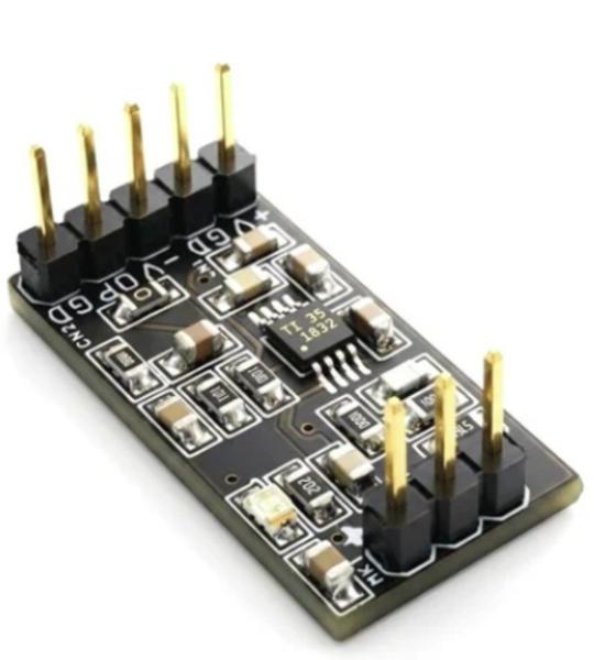
The TLV6741 is a 10 MHz op amp with low broadband noise. Its small SC70-5 package and low operating voltage make it well suited to this kind of preamplifier circuit.
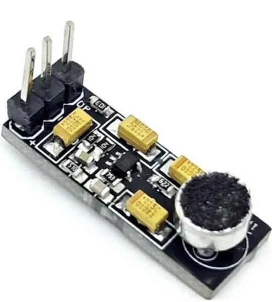
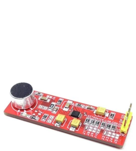
This 3-wire microphone pre-amplifier is designed using the low-power, low-noise, and low-distortion OPA1692 audio operational amplifier, making it ideal for high-performance electret microphone applications. The circuit is optimized for electret microphones that use a 3-wire interface, providing excellent audio quality while maintaining minimal power consumption.
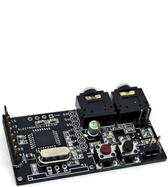
The idea is to simplify the hardware and make audio connections easier. Just upload the Arduino code to the microcontroller, connect the audio source, and you'll experience the echo effect immediately. The project is designed to be simple and user-friendly, allowing anyone to enjoy it.
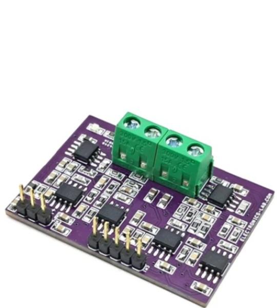
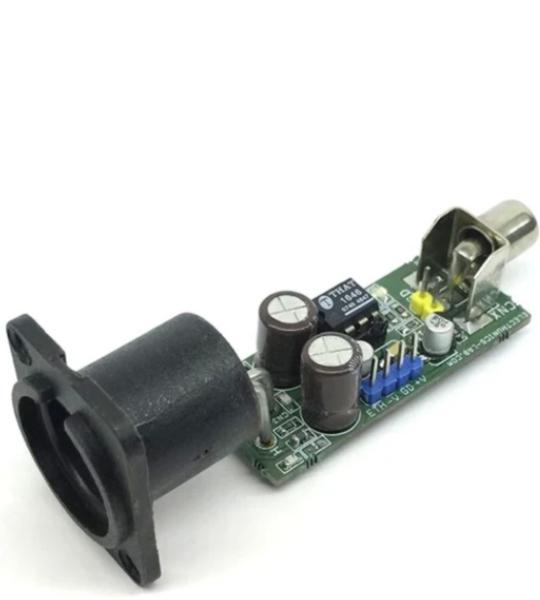
This audio-balanced line driver project enables to drive hundreds of feet in length of cables without becoming unstable The project is based on the THAT1646 chip, which is a new generation monolithic differential line driver that offers improved performance over conventional cross-coupled designs. Based on high performance, fully differential op-amp exhibits low noise and distortion, high slew rate, and wide output swing. Output is very stable when driving difficult loads, and output is short-circuit protected. The operating power supply is +/-15V DC, XLR, and RCA connector provided for output and input. D1, D2 are the Power LEDs, C7 decoupling capacitor, Ferrite Bead L1, L2, capacitor C6, C8, C9 take cares of RFI noise, Capacitors C5, and C10 acouple the common-mode feedback loop. This changes the loop operation from serving the common-mode output current at audio frequencies to serving the common-mode output voltage to 0 at DC. This results in much lower common-mode output offset voltage. D1 +VCC Power LED, D2 -VEE Power LED, CNX-J1 single-ended unbalanced audio input, CN3 Male XLR balanced audio output, CN1 power input, CN2 or J1-CNX audio input.
This is a complete microphone signal conditioning project. Designed primarily for voice-band applications, this project provides amplification, limiting, variable compression, and noise gate. User-adjustable compression ratio, noise gate threshold, and two different fixed gains optimize circuit operation for a variety of applications.
The project presented here is a professional quality Phantom powered Microphone pre-amplifier. The project is built using the INA163 chip from TI. The Chip is a very low-noise, low-distortion, monolithic instrumentation amplifier. R2 and R3 provide a current path for a conventional 48V phantom power source for a remotely located microphone. A slide switch SW1 allows phantom power to be disabled. C6 and C8 block the phantom power voltage from the INA163 input circuitry. Additional input protection against ESD and hot-plugging, four 1N4148 diodes D1, D2, D3, D4 connected from the input to supply lines. R7 and R8 provide a path for the input bias current of the INA163. Gain is set with a variable resistor, PR1, in series with R4. R4 determines the maximum gain. The total resistance, R4 + PR1, determines the lowest gain. A special reverse-log taper potentiometer for PR1 can be used to create a linear change (in dB) with rotation. LED D5 is used as a power indicator. L1, L2, C7, C10, and C11 components protect the inputs from EMI and RFI noise.
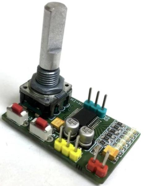
The project described here is a compact stereo volume and balance control with rotary encoder. It provides 32 log potentiometer steps with buffered wiper output. The project can easily replace mechanical potentiometer. 5 LEDs indicate the volume level or balance settings , depending on the status of the mode indicator D1 LED. The MAX5440 includes debounced pushbutton inputs for mute and mode. The mute input allows a single pushbutton to change between volume control and the -90dB (typ) mute setting. The mode input toggles between volume and balance control. A click-and-pop suppression feature minimizes the audible noise generated by wiper transitions.
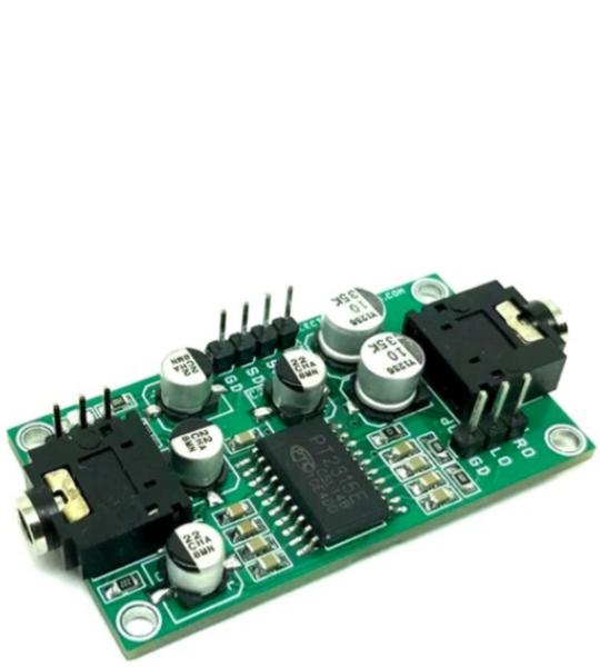
This PT2315E IC-based audio processor is designed for versatile applications and includes master volume control with low-frequency loudness compensation, speaker output attenuator, and tone control. It is a good solution for home audio signal processing. Due to the high-reliability requirement from the audio business, the PT2315E improves both audio performances and input surge current capability and these cause the PT2315E to be the best solution for the cost-effective audio systems.
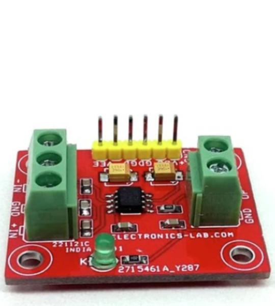
The project described here is a differential line receiver consisting of high-performance INA134 OPAMPs with on-chip precision resistors. The project is fully specified for high-performance audio applications and has excellent AC specifications, including low distortion (0.0005% at 1kHz) and high slew rate (14V/µs), assuring good dynamic response. In addition, wide output voltage swing and high output drive capability allow use in a wide variety of demanding applications. The INA134 on-chip resistors are laser trimmed for accurate gain and optimum common-mode rejection. Furthermore, excellent TCR tracking of the resistors maintains gain accuracy and common-mode rejection over temperature. Operating power supply ±4V to ±18V (8V to 36V total supply).
The board presented here is a preamplifier for contact microphones that are used for amplifying the sound of musical instruments which do not contain electrical pickups, such as guitar and violins. Most contact microphones use a piezo element to convert vibration in the body of the musical instrument to a voltage. The circuit is built using OPA1678 OPAMP. The low noise and low input bias current of the OPA1678 makes the device an excellent choice for high impedance preamplifiers for piezo elements. This preamplifier circuit provides high input impedance for the piezo element but has low output impedance for driving long cable runs. It provides a balanced audio output that can be fed to a balanced microphone pre-amplifier. The circuit has also the option for phantom power input. Install R3=1.2K Ohms, R2=1.2K Ohm and Zener diode 24V.
Cookie preferences