USD
USD INR
INR
Call Us Now
+91 9106756572
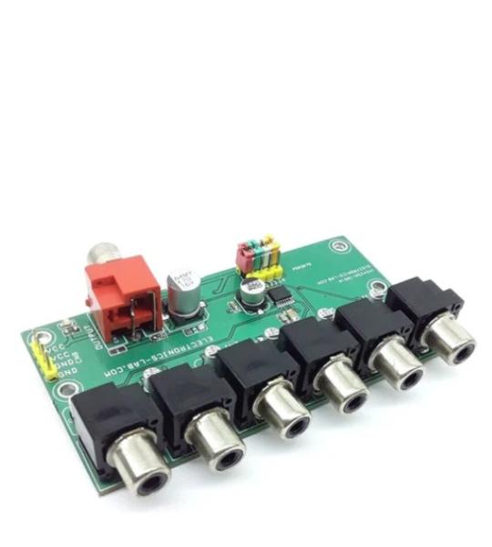
The project presented here is a video driver with 6 channel input selection using onboard jumpers or a microcontroller interface. The circuit features a wide dynamic range and frequency response. The IC can be used with low voltage starting at VCC=2.8V and the project supports a broad range of input signals, depending on whether or not a 6-dB video and video driver is included and what combination of sync tip clamp type and bias (resistor terminal) type input is used. RCA connectors are provided for video input and output connection. The header connector helps to power the board. Jumpers J2 to J3 are provided to select the input channels. 6-channel video selection can also be controlled using an external circuit or microcontroller by applying high or low TTL signal to CTLA, CTLB, CTLC, CTLD pins. In this case, use the center pins of jumper J1 to J4.
D105
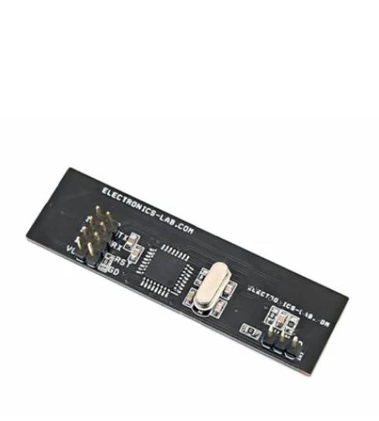
This Fuel level Monitor allows users to measure the fuel level using a resistive float sensor in the fuel tank. The project measures the fuel level and displays it on a 15-segment bar-graph display. The project is Arduino-compatible and consists of ATMEGA328 controller. The resistive sensor with a divider resistor is connected to Analog pin A0 of the MCU chip. The 15 LEDs of different colors are connected to various Arduino pins.
D107
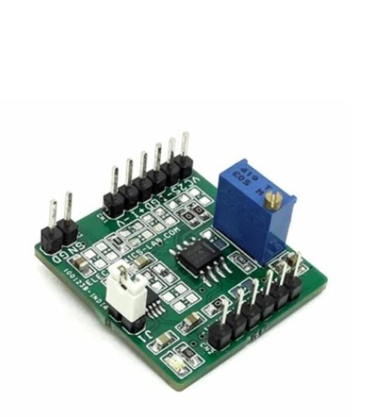
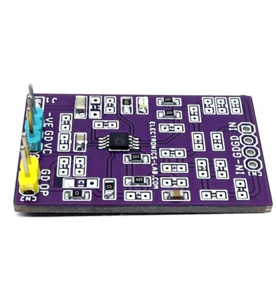
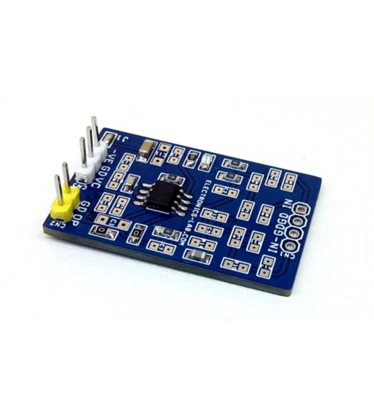
This is a universal instrumentation amplifier module for SOIC8 package. Various configurations are possible by selecting the right components. The board helps users to develop instrumentation amplifier circuits and it can accommodate SOIC8 devices such as INA828 from Texas Instruments. All capacitors are ceramic type size 0805 and resistors are also size 0805. It supports dual supply or single supply, install R12 0 Ohms for a single supply usage. Various capacitors and resistors can be installed as per application requirements. D1 is the Power LED. Board also has 2.5V precision reference voltage chip. Jumper J1 is provided to select the 2.5V reference voltage to the IN828 Amplifier. An external reference voltage can be fed through CN1 or CN2 Pin 2, Open Jumper J1 in this case. The project also consists of resistors R3, R4, R7, and R8 to create bridge configurations for various sensors. CN3 is provided for sensor input.
D112
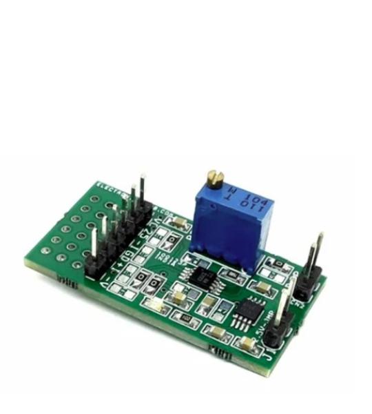
This is a universal instrumentation amplifier module that can be used to develop and test instrumentation amplifier circuits. The board can accommodate VSSOP8 devices such as INA126, INA333, INA155, INA156 from Texas Instruments. All capacitors are ceramic type with size 0805 and resistor size is also 0805. It supports dual supply or single supply. You should install R8 0 Ohms for a single supply usage. Various capacitors and resistors can be installed as per application requirements. D1 Power LED. Board has also a 2.5V precision reference voltage chip. Jumper J1 is provided to select the 2.5V reference voltage to the INA333 Amplifier. An external reference voltage can be fed through CN1 Pin 2. In this case Open Jumper J1. Also, a small prototyping area is provided.
D113
This is easy to build and very useful project for hobbyists and students to learn and create op-amp-based projects. The board accommodates a single op-amp in DIP-8 package. The project provides the user with multiple choices and extensive flexibility for different applications circuits and configurations. It provides the user with many combinations for various circuit types including active filters, differential amplifiers, and external frequency compensation circuits etc. A few examples of applications circuits are given below. LM358 op-amp is the right choice to use or any DIP-8 op-amp with the same pin configuration as LM358 can be used. It supports dual supply or single supply, Jumper J1 is provided to use this board with a single supply, D1 power LED.
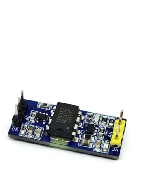
This Isolated Analog Input module is designed for interfacing a wide range of analog signals from sensors and field devices. It is ideal for process control, factory automation, and various industrial applications.
The module simplifies the task of connecting analog voltages or sensors to Arduino boards or other microcontrollers while ensuring complete optical isolation. It requires two separate 5V DC power supplies – one for the input side and one for the output side.
By default, the module accepts a 0–5V analog input and provides an optically isolated 0–3.3V output.
To use the module, connect your sensor or analog voltage to the input side, and wire the output to an analog pin of an Arduino or the ADC input of any microcontroller.
The design is based on an optically isolated linear optocoupler with an isolation voltage rating of 3750V. The IC2 MCP601 operates as a closed-loop servomechanism, sensing the photodiode current and driving the optocoupler’s LED. IC1 is the linear optocoupler itself, while IC3 MCP601 serves as a signal conditioner for the phototransistor output. A D1 power LED indicates the input-side power status.
The LOC110 Single Linear Optocoupler features an infrared LED optically coupled with two photodiodes. One feedback (input) photodiode is used to generate a control signal that provides a servomechanism to the LED drive current, thus compensating for the LED’s nonlinear time and temperature characteristics. The other (output) photodiode provides an output signal that is linear to the servo LED current. The IC features wide bandwidth, high input-to-output isolation, and excellent servo linearity.
D115
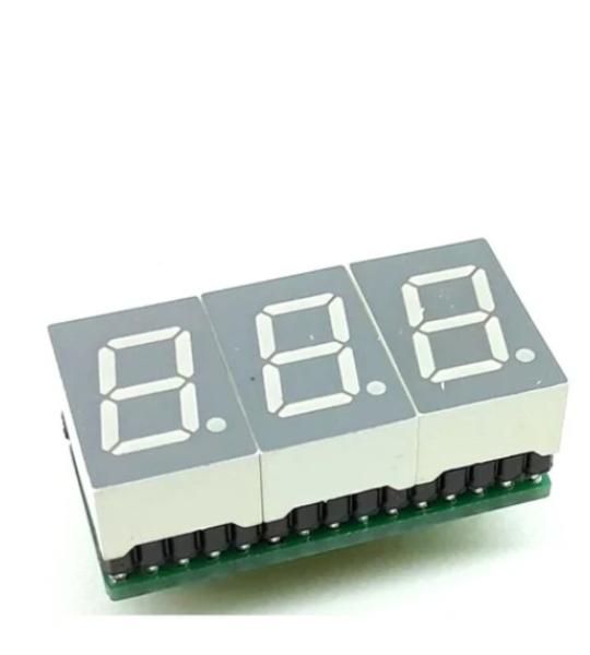
This is a 3 Digit 7-segment display project that contains 3 x Common Cathode displays, current limiting resistors or each LED segment, 3 x PNP Transistor on each common cathode for multiplexing etc. The project works with 5V TTL signals but can be optimized for 3.3V operations by reducing the current limiting resistors' value.
D116
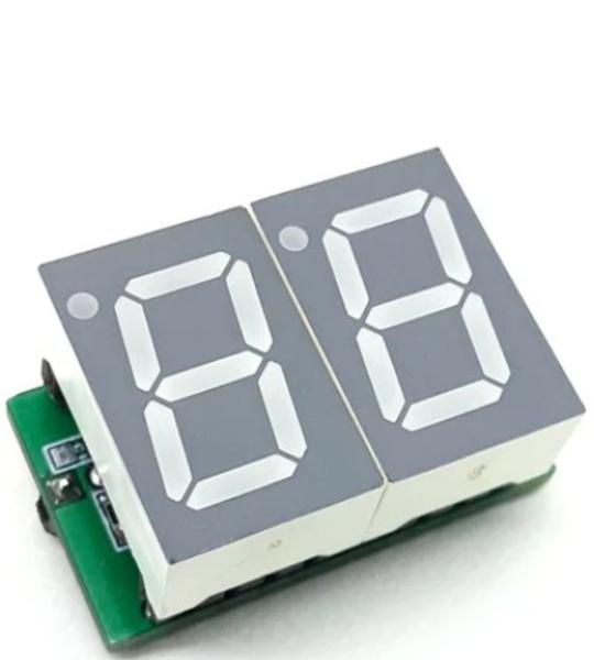
This 2 Digit 7 segment display project contains 2 x Common Cathode displays, current limiting resistors or each LED segment, 2 x PNP Transistor on each common cathode for multiplexing, etc. This is a very compact project that works with 5V TTL signals but can be optimized for 3.3V operations by reducing current limiting resistors’ value. Header connector provided for easy interface to Arduino or other microcontrollers. All inputs are compatible with TTL 5V signals.
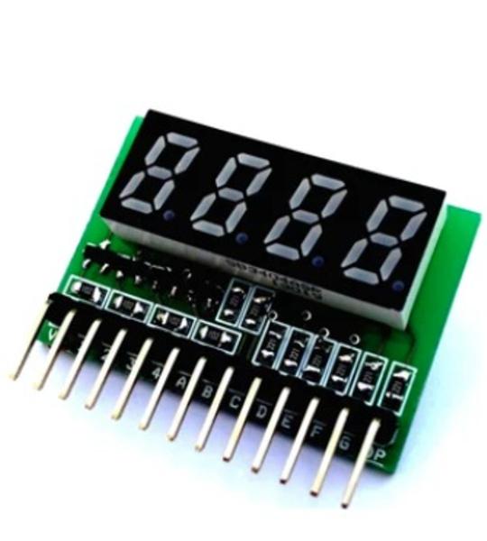
7 Seven segment multi-plexed display is tiny board that has been designed around Common Anode 4 digit Display, Display has 12 Pins. The board is provided with current limiting resistors on all LED segments and 4 PNP Transistors to drive 4 digits, the project is ideal for easy micro-controller interface with 13 pin Header connector. The Board supports 3.3V as well 5V TTL interface .
D117
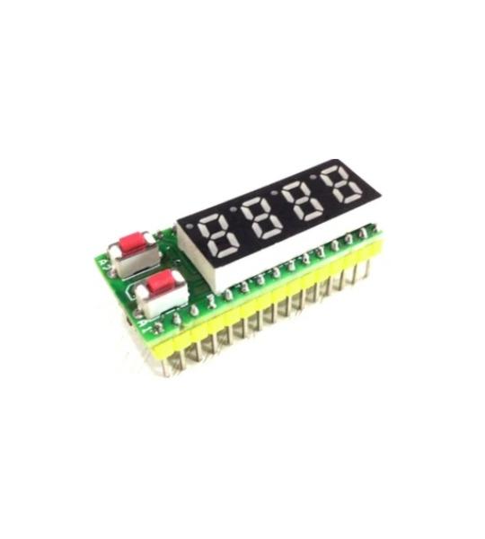
4 Digit Multiplexed display shield for Arduino Nano with on board 2 tactile switches and LM35 temperature sensor. This shield helps you to develop many projects that require 4 digit display. For example a thermometer can be made using on board LM35 sensor. 7 Seven segment multiplexed display is a tiny board and has been designed around Common cathode 4 digit Display. Display has 12 Pins. The board is provided with current limiting resistors on all LED segments and 4 NPN Transistors to drive 4 digits. This tiny board directly seats on Arduino Nano. Nano analog pin A0 connected to LM35 sensor, A1 and A2 connected to Switch 1 and switch 2 with pull down resistors. Digital pin D2-D8 connected to displays segment A-F, Digital pin D9 connected to DP of display, D10-D12 pins are associated to Digit 1-4 common cathode.
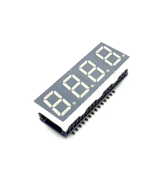
This 4 Digit 7 segment display project contains 4 x Common Cathode displays, current limiting resistors or each LED segment, 4 x PNP transistors on each common cathode for multiplexing, etc. This is a very compact project that works with 5V TTL signals but can be optimized for 3.3V operations by reducing current limiting resistors values.
This 4 Digit 7 segment display project contains 4 x Common Cathode displays, current limiting resistors or each LED segment, 4 x PNP transistors on each common cathode for multiplexing, etc. This is a very compact project that works with 5V TTL signals but can be optimized for 3.3V operations by reducing current limiting resistors values. A header connector is provided for easy interface to Arduino or other microcontrollers. All inputs are compatible with TTL 5V signals.
D119
This is easy to build and very useful project for hobbyists and students to learn and create OPAMP-based projects. The project accommodates a single op-amp in a SOIC-8 package. The project provides the user with multiple choices and extensive flexibility for different applications circuits and configurations. It provides the user with many combinations for various circuit types including active filters, differential amplifiers, external frequency compensation circuits etc. A few examples of application circuits are given below. LM358 op-amp is the right choice to use but any SOIC8 OPAMP with the same pin configuration can be used. It supports dual supply or single supply, Jumper J1 is provided to use this board with a single supply, D1 is the power LED.
Cookie preferences