USD
USD INR
INR
Call Us Now
+91 9106756572
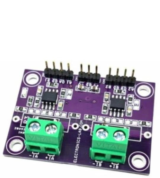
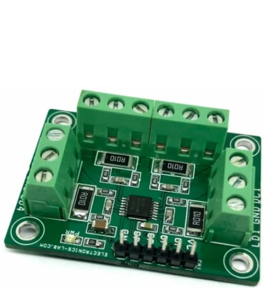
This board is built using a 2 x INA149 precision unity-gain difference amplifier with a very high input common-mode voltage range. The project can be used as a current sensor for high-voltage applications, INA149 provides a common-mode voltage range of +/-275V. The project operates with a wide supply range from +/-5V to +/-15V. The circuit measures current by sensing the voltage drop across a series of resistors RS, R4, and R12. The application circuit shows the INA149 used to measure the supply currents of a device under test. The sense resistor imbalances the input resistor matching of the INA149, thus degrading its CMR. Also, the input impedance of the INA149 loads RS, causes a gain error in the voltage-to-current conversion. Both of these errors can be easily corrected.
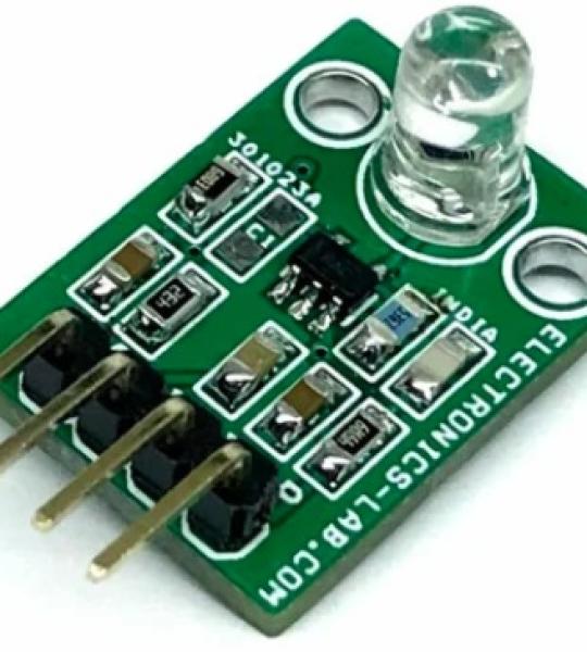
This small module is a photodiode amplifier. The circuit consists of an OPAMP configured as a transimpedance amplifier for amplifying the light-dependent current of the photodiode. A small bias voltage is derived from the positive supply and applied to the op amp’s non-inverting input. This prevents the output from saturating at the negative supply rail in the absence of input current. For this design, the photodiode operates in photoconductive mode: exposure to light will cause a reverse current through the photodiode. The diode is connected such that this current causes the OPAMP output voltage to increase. The feedback capacitor C5 helps to maintain stability. This capacitor compensates for the photodiode capacitance at the inverting input of the OPAMP. Finally, in the absence of any photodiode current, the amplifier output will attempt to settle at the voltage applied to the non-inverting input. If the non-inverting input is grounded, the output voltage would ideally be 0V. However, the output voltage can never reach 0V because this is also the value of the negative power supply. Therefore, the OPAMP output will “saturate” near its negative power supply. This condition is undesirable and can delay the amplifier’s response to an input signal. To avoid saturation, a resistor divider R1 and R2 from the positive supply is used to bias the amplifier input above ground. The output swing of this amplifier is from 0.1V to 4.9V. The project was built using OPA320 OPAMP which is a new generation of precision, low-voltage CMOS operational amplifiers optimized for very low noise and wide bandwidth while operating on a low quiescent current of only 1.45 mA.
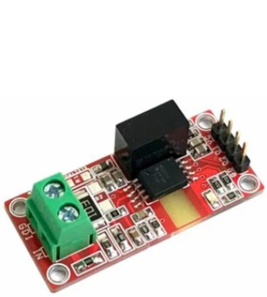
This high-speed, isolated Undervoltage and Overvoltage detection project is implemented with a dual isolated window comparator with an adjustable threshold (AMC23C14). This circuit is designed for industrial field-supply applications where the controller side must detect whether the remote module supply voltage is in a valid range.
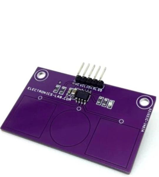
The project described here is a 3 channel capacitive touch sensor based on CAP1203 chip from Microchip which is a multiple-channel capacitive touch sensor controller. It has 3 x individual capacitive touch sensor inputs with programmable sensitivity for use in touch sensor applications. 3 x touchpads are provided on PCB to detect the touch. Each sensor input is calibrated to compensate for system parasitic capacitance and automatically recalibrated to compensate for gradual environmental changes. The CAP1203 includes Multiple Pattern Touch recognition that allows the user to select a specific set of buttons to be touched simultaneously. If this pattern is detected, a status bit is set and an interrupt is generated. The CAP1203 has Active and Standby states, each with its own sensor input configuration controls. Power consumption in the Standby state is dependent on the number of sensor inputs enabled as well as averaging, sampling time, and cycle time. Deep Sleep is the lowest power state available, drawing 5µA (typical) of current. In this state, no sensor inputs are active, and communications will wake the device.
This angle sensor module features an ADA4571 chip, an anisotropic magneto resistive (AMR) sensor with integrated signal conditioning amplifiers and ADC drivers. The circuit produces two analog outputs that indicate the angular position of the surrounding magnetic field.
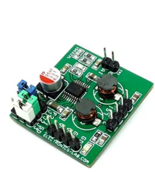
This 4-Channel current sense amplifier is designed for cost-optimized applications. This is a current-sense amplifier (also called a current-shunt monitor) that senses the voltage drop across current-sense resistors at common-mode voltages from –0.2 V to +26 V, independent of the supply voltage. The project was built using INA4180 chip which integrates a matched resistor gain network in four, fixed-gain 20V/V, this matched gain resistor network minimizes gain error and reduces the temperature drift. The board operates with a single 2.7-V to 5.5-V power supply. The four-channel INA4180 draws a maximum supply current of 900 µA. Resistors R2, R6, R8, R12, R3, R7, R9, R13 and Capacitor C3, C4, C5, C6 used as input filters. The gain of the amplifier is 20V/V, and external input resistors resulting a 0.9% gain error.
This is a compact size, mono, switch-mode (Class-D) audio power amplifier intended for multimedia and general-purpose high-power applications. It has greater than 87% efficiency and is capable of delivering 2W maximum continuous power to a 4Ω load. The project is designed to be driven by the line-out or headphone jack of a CD/MP3 player or to be directly connected to any audio source. The project includes header connectors for speakers, power supply, and audio input for quick connection. The project also has 3x jumpers for frequency selection and shutdown action. The project is built using the MAX4295 chip.
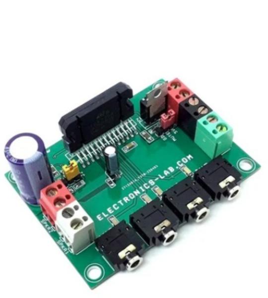
This is an AB class audio amplifier based on the TDA7388 chip and it is a great choice for car audio applications. This compact board has 4 channels each 26W with 4 ohms speaker. Then IC consists of a fully complementary PNP/NPN configuration and the TDA7388 allows a rail-to-rail output voltage swing with no need for bootstrap capacitors. The extremely reduced boundary components count allows very compact sets. The TDA7388’s inputs are ground-compatible and can stand very high input signals (±8 Vpk) without any performance degradation. The standard value for the input capacitors (0.1 µF) is adopted, and the low-frequency cut-off amount to 16 Hz. 4 x 3.5 mm stereo EP socket helps to feed audio signals, and the onboard screw terminal makes life easy for speaker connections, and the power supply input. Onboard jumpers are provided to select the standby and mute function. D1 indicates power present. Mounting a proper heatsink is very important for chip health.
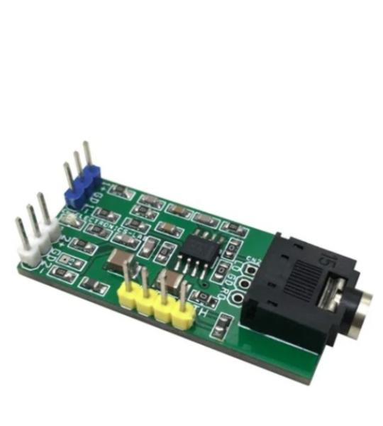
This is a headphone amplifier project for audio digital-to-analog converters (DACs) with differential voltage outputs. This circuit converts the differential voltage output of the DAC to a single-ended, ground-referenced signal and provides the additional current necessary for low-impedance headphones. Project is built using OPA1688 low distortion, high-drive Sound Plus audio amplifier. The circuit tested with dual +/-5V DC supply, and it can drive a load 16 Ohms to 600 Ohms. Headphone amplifier provides an output 50mW into 32 Ohms. Signal for the right channel and left channel input is applied to the amplifier through connectors CN1and CN3, respectively.
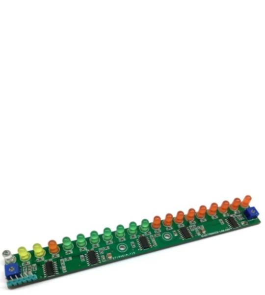
This is an “Audio VU Meter” or “Sound Level Meter”, it is a general-purpose bar-graph Audio VU meter designed for fun projects. All you need is to hook up one wire to the output of the audio amplifier’s speaker pin along with GND and see the magic. The response of the circuit is very fast and it provides beautiful visual representation from audio input signal.
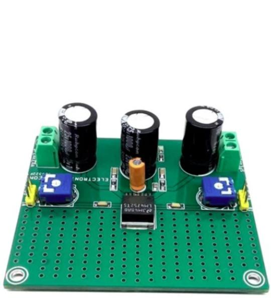
The Stereo Audio Amplifier project shown here is capable of delivering 2.5W per channel of continuous average output power to 4Ω loads using a single 12V supply at 10% THD+N. The project is built using the LM4752 chip. This chip is specifically designed for single supply operations and low external components count. The gain and bias resistors are integrated on-chip, resulting in a 2.5W stereo amplifier in a compact 7-pin TO263 SMD package. High output power levels at 12V supplies and low external component count offer high value for compact stereo and TV applications. Sufficient power dissipation is provided on PCB so no external heatsink is required for IC.
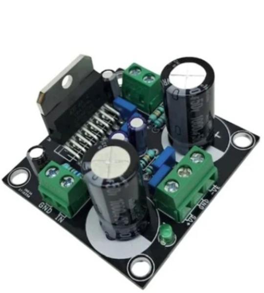
The 60 W Class-AB Audio Amplifier is a single-channel power amplifier board built around the STMicroelectronics TDA7296. This Class-AB amplifier is suited to a wide range of applications, including home stereo systems, self-powered speakers, and high-end televisions.
Cookie preferences