USD
USD INR
INR
Call Us Now
+91 9106756572
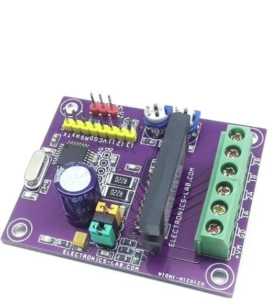
This is an Arduino compatible board that contains an Atmega328 microcontroller and Bipolar Stepper Motor Driver chip STK682-010. This Hybrid IC from ON Semiconductor can deliver up to 2.5A current and it can have an input supply up to 32V DC. It has multiple micro-stepping options such as Full step, 1/2th Step, 1/4th Step, 1/8th Step, 1/16th Step, 1/32th Step, 1/64th Step, 1/128th Step. PR1 trimmer potentiometer is provided to set the decay, 3.5V Slow Decay, 1.1V to 3.1V Mixed Decay, 0.8V-1V Fast Decay, and PR2 Trimmer Potentiometer provided to set the output current. Chopping frequency set to 83.3 Khz using capacitor C5 100PF. Micro-Stepping can be set with the help of jumper J1, J2, J3. This board is by default enabled since the enable pin has a pull-up resistor, but you can provide a low signal to disable the motor driver chip. Atmega328D provides Direction pulse, Step pulse, Enable control, etc. The IC has built-in automatic half current functions to reduce the vibrations & current while the motor is in static mode. It is important to use a heatsink on the motor driver chip. Refer to the micro-stepping table to set the micro-stepping. Board requires a Motor power supply as well logic supply 5Vdc.
This is an Arduino compatible board that contains an Atmega328 microcontroller and Bipolar Stepper Motor Driver chip STK682-010. This Hybrid IC from ON Semiconductor can deliver up to 2.5A current and it can have an input supply up to 32V DC. It has multiple micro-stepping options such as Full step, 1/2th Step, 1/4th Step, 1/8th Step, 1/16th Step, 1/32th Step, 1/64th Step, 1/128th Step. PR1 trimmer potentiometer is provided to set the decay, 3.5V Slow Decay, 1.1V to 3.1V Mixed Decay, 0.8V-1V Fast Decay, and PR2 Trimmer Potentiometer provided to set the output current. Chopping frequency set to 83.3 Khz using capacitor C5 100PF. Micro-Stepping can be set with the help of jumper J1, J2, J3. This board is by default enabled since the enable pin has a pull-up resistor, but you can provide a low signal to disable the motor driver chip. Atmega328D provides Direction pulse, Step pulse, Enable control, etc. The IC has built-in automatic half current functions to reduce the vibrations & current while the motor is in static mode. It is important to use a heatsink on the motor driver chip. Refer to the micro-stepping table to set the micro-stepping. Board requires a Motor power supply as well logic supply 5Vdc.
Arduino code is provided to test the board. The user will be able to control stepper motor speed using a 10K potentiometer connected to Analog pin A0 using connector U3. Users may write their own code to drive the motor as per requirements, micro-stepping is separate and independent from micro-controller. Only Pulse/Clock input, Direction, enable pins are connected to Arduino hardware.
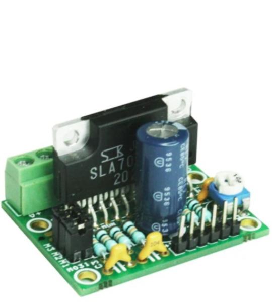
This tiny Unipolar stepper motor driver has been designed around SLA7078MPR IC from Sanken. It is a unipolar stepper Motor driver that can handle current up to 3 Amps and has micro-stepping up to 1/16 steps. On-board Jumpers are available to set the Micro-stepping and Preset (Potentiometer) to set the current.
The SLA7078MPR series motor driver ICs features unipolar drivers. The clock-in type input interface allows simplified control logic, and options for built-in sense current detection and load circuit short or open protection (patent pending) provide lower loss, and lower thermal resistance.
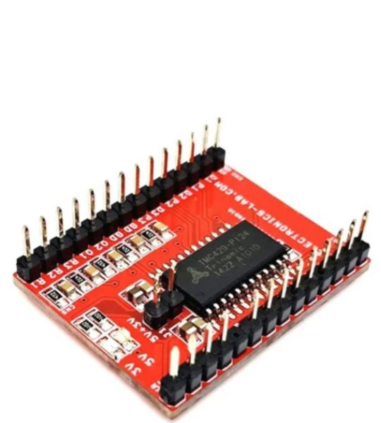
This TMC429 Breakout Board is a versatile motion control solution that enables users to create sophisticated three-axis motion control systems. This board interfaces with the TMC429 chip through SPI communication and provides 3-axis step/direction output signals along with limit switch inputs.
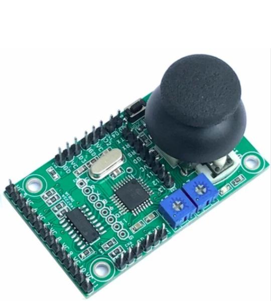
This is a pulse generator for a stepper motor driver using a joystick. It is a board that contains an Arduino-compatible microcontroller and circuitry for controlling up to 2-channel (2-axis) stepper motors. The board has multiple options to develop stepper motor-related control systems, from a 2-axis analog joystick to a trimmer potentiometer to a 7-channel open collector TTL output to interface stepper drivers with optocoupler inputs, etc.
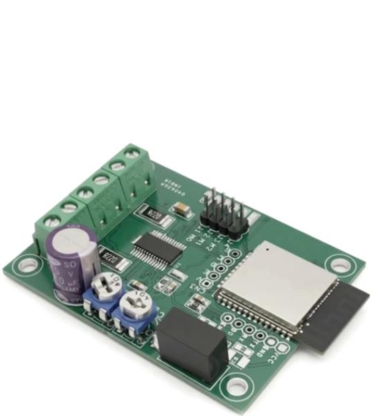
This Wi-Fi Stepper Motor Driver enables remote control of a bipolar stepper motor over a wireless network. The project is based on the ESP32 Wi-Fi microcontroller and the BD63731EFV stepper motor driver IC, providing a compact and reliable solution for motion control applications.
The driver operates from a 24 VDC power supply and is capable of driving bipolar stepper motors with output currents of up to 3A. The BD63731EFV supports multiple micro-stepping modes, allowing smooth and precise motor operation while reducing vibration and audible noise.
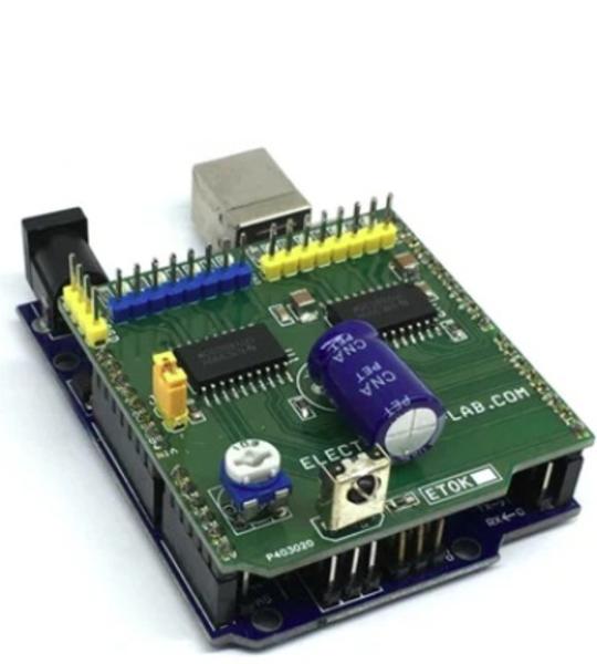
The 8 Channel Driver Arduino UNO Shield is designed to enable users to switch inductive loads for up to 800mA each channel and up to 24V DC with no heat-sink needed. It is ideal for such applications as driving 2x unipolar stepper motors, solenoids, relays, and small DC motors. It uses 2x DRV8803 Chip from Texas instruments which is 4 channel low side driver with over current protection. IC’s Internal shutdown protection function is provided for overcurrent protection, short circuit protection, under-voltage lockout, and over temperature. Faults are indicated by a fault output pin that is normally high and goes low if a fault condition occurs. Reset and enable pins has internal pull-down resistors.
Cookie preferences